I decided to try and design a small module using the ESP32 D2WD with 2 MByte embedded flash. This is partly because it is convenient to have a solution that can be dropped into a more complex design to provide wifi/BLE as well as the fact that soldering the D2WD is a pain and having a batch of these produced would greatly ease assembly of custom designs using this great IC.
The design is available here: https://www.oshpark.com/shared_projects/pDlybNo8
It should work but I haven't tested it yet so buyer beware. But it is based on my dev board design using the same IC so I expect it to work with the right external connections. GPIO0 and nRST are already pulled up, GPIO12 is also setting the flash to 1.8 V. I would put GPIO0 and nRST on buttons to ground the former while toggling the latter for boot mode. I would also use an FTDI USB-to-UART converter on RX/TX for programming and USB serial output. But other configurations are also possible depending on the application.
I expect it will be easier for the user (me!) to solder the module using low temperature solder paste and a hot air gun than it is to solder the ESP32-D2WD plus passives so this will save me a lot of work once I get a batch made in China.
I should probably replace the monopole with a good chip antenna and maybe think about adding mounting points for a steel cover. But this prototype design will be enough for me to test function and see how mnuch easier it is to work with.
ESP32 D2WD Module Design
- Vader_Mester
- Posts: 300
- Joined: Tue Dec 05, 2017 8:28 pm
- Location: Hungary
- Contact:
Re: ESP32 D2WD Module Design
I have just 2 things to add:
The next revision should use the PICO-D4, which is a 7x7mm size package, with dual core ESP, 4MB flash and crystal inside, also with matching components for 50ohm transmission line.
With that one you can basically put a PICO on your module wire our the GPIO pins to the board edge contacts, solder a chip antenna, no additional mathicng circuit is needed, and there you go. As passives you will only need some input caps for the VDD.
Additioanlly, using castellated edges (like on the WROOM), the soldering of the module is much better.
For higher quantities and price, I suggest Seeedstudio where they can make thinner modules.
Analoglamb is selling PICO modules.
Datasheet: https://www.espressif.com/sites/default ... eet_en.pdf
(I have a basic footprint done in Designspark PCB, and have a DXF file for the solder footprint design of the PICO).
Insides of the PICO:

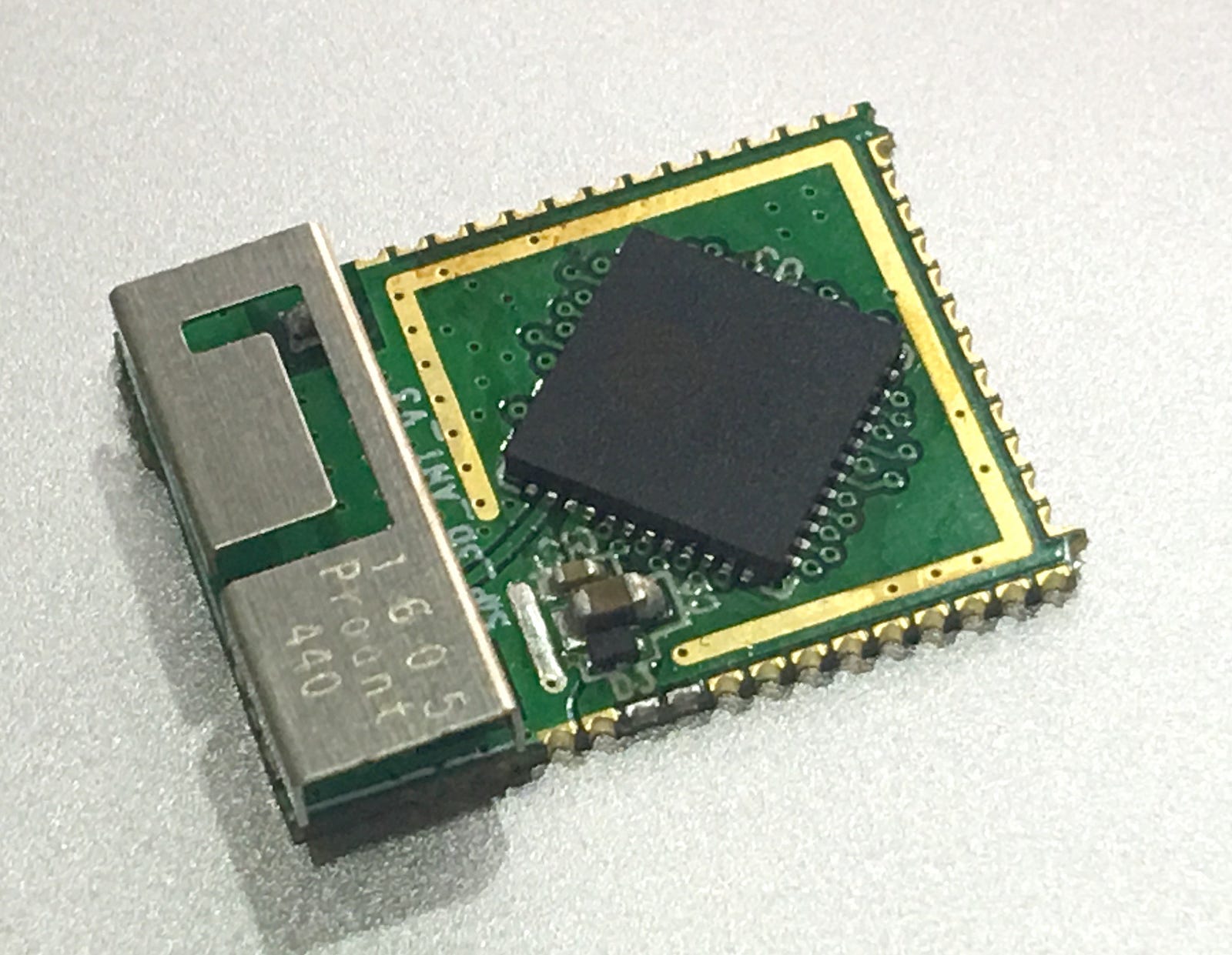
Example of a PICO module found on the net (this one uses a PROant 440, and about 14mm wide)

Vader[BEN]
The next revision should use the PICO-D4, which is a 7x7mm size package, with dual core ESP, 4MB flash and crystal inside, also with matching components for 50ohm transmission line.
With that one you can basically put a PICO on your module wire our the GPIO pins to the board edge contacts, solder a chip antenna, no additional mathicng circuit is needed, and there you go. As passives you will only need some input caps for the VDD.
Additioanlly, using castellated edges (like on the WROOM), the soldering of the module is much better.
For higher quantities and price, I suggest Seeedstudio where they can make thinner modules.
Analoglamb is selling PICO modules.
Datasheet: https://www.espressif.com/sites/default ... eet_en.pdf
(I have a basic footprint done in Designspark PCB, and have a DXF file for the solder footprint design of the PICO).
Insides of the PICO:

Example of a PICO module found on the net (this one uses a PROant 440, and about 14mm wide)

Vader[BEN]
Code: Select all
task_t coffeeTask()
{
	while(atWork){
		if(!xStreamBufferIsEmpty(mug)){
			coffeeDrink(mug);
		} else {
			xTaskCreate(sBrew, "brew", 9000, &mug, 1, NULL);
			xSemaphoreTake(sCoffeeRdy, portMAX_DELAY);
		}
	}
	vTaskDelete(NULL);
}Re: ESP32 D2WD Module Design
I have a question on the pinout of the esp-pico-kit.
I think the pinouts of the data on the pico website do not match the pinouts in the data sheet.
My summary: ESP32-PICO-KIT.pdf
Pinout from website: http://esp-idf.readthedocs.io/en/latest ... o-kit.html
Pin allocation from datasheet: esp32-pico-d4_datasheet_en.pdf
I think I have attached a png/pdf that shows the issues.
The pinout on the pico website shows different GPIOs assigned to the SD interface, compared to the pinots in the esp32-pico datasheet.
In particular, GPIO9 and GPIO10.
Can you clarify which is correct?
- Attachments
-
- ESP32-PICO-KIT.png (378.94 KiB) Viewed 10512 times
Who is online
Users browsing this forum: No registered users and 48 guests
