Problem with Custom PCB Design

MooseXMTP
Posts: 9
Joined: Sun Jan 01, 2023 4:40 pm

Problem with Custom PCB Design

Postby MooseXMTP » Mon Dec 25, 2023 7:12 pm

Hi,

I designed a custom PCB for the ESP12F and BME680. It's quite simple - it has an AMS1117 to step down 5V from a USB port to 3.3V, the ESP and BME, some pins for RX and TX for programming, and jumpers to connect IO2 to HIGH and IO15 to GND (I read online that you need to connect this for programming). From what I know this is everything I need to make this function.

However, even after the flashing process seemingly worked, I can't get the board to connect to ESPHome (I want this to be a sensor for my smart home). Just to be sure the ESP8266 isn't dead I bought an ESP12F programmer and flashed the chip that way after desoldering it from my PCB. After flashing it using that it connected with no problem, so I soldered it back onto my PCB and as soon as I did that it stopped working again.

I tried to look online at how other people design their PCBs and from what I can tell they do as I did for my PCB.

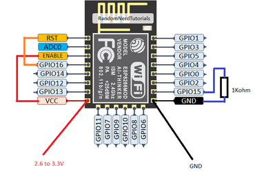
I am really out of ideas and hope that someone knows what the problem is. I attached a photo of my schematic - maybe theres a problem there.

Thanks :D
Attachments
ESP8266 Schematic.PNG
ESP8266 Schematic.PNG (35.2 KiB) Viewed 2490 times

User avatar
Inq720
Posts: 35
Joined: Fri Dec 22, 2023 1:36 pm
Location: North Carolina, USA
Contact:

Re: Problem with Custom PCB Design

Postby Inq720 » Mon Dec 25, 2023 7:50 pm

I'm not sure that I'm reading all the details of your schematic, but I see two missing parts. The bare ESP-12 boards (non Wemos, NodeMCU) can't be programmed OR run as they come. You appear to have the logic wiring that will allow you to program it, but don't have the ones necessary for it to run. You need:
  • a pull-down resistor between GPIO15 and GND. I've seen anywhere from 1K to 10K will work. I'm currently using 1K and works fine.
  • a pull-up resistor between ENABLE and VCC. Also 10K will work. It looks like you do have this powered directly which works also, but a pull-up resistor on it, allows you to use the pin for I/O during runtime.
I had the same problem, and here is a thread on another forum charting the details - https://forum.dronebotworkshop.com/help ... post-43703

Image

MooseXMTP
Posts: 9
Joined: Sun Jan 01, 2023 4:40 pm

Re: Problem with Custom PCB Design

Postby MooseXMTP » Tue Dec 26, 2023 8:53 am

Hi, I added the resistor and it still doesn't work.

As additional information:

In my ESP12F programmer, the chip is in boot mode 3;6 during normal operation (it works then). And when I checked the boot mode in my circuit (before adding the things you mentioned) the logs also show boot mode 3;6. This is even more confusing to me. I found these websites talking about boot modes and they all correlate to what I did on my PCB: https://riktronics.wordpress.com/2017/1 ... explained/
https://github.com/esp8266/esp8266-wiki ... ot-Process

Also, when the chip is in the ESP12F programmer after the initial log readouts it logs wifi connection status, however on my PCB it doesn't get to that step - maybe it's starting the boot but not getting to the program somehow. Perhaps there is some other GPIO to pull down.

I hope this information helps :D

User avatar
Inq720
Posts: 35
Joined: Fri Dec 22, 2023 1:36 pm
Location: North Carolina, USA
Contact:

Re: Problem with Custom PCB Design

Postby Inq720 » Tue Dec 26, 2023 3:14 pm

On my first post, I just noted that you didn't have the resistors that I was expecting and that common breakout boards have...
BOB.png
BOB.png (168.07 KiB) Viewed 2219 times
I see now if your J4 jumpers are in, they'll do the same thing.

I can think of one other thing - If TX is pulled LOW on your schematic at boot, it'll fail.

Anyway, here as wired above working:
Mine.jpg
Mine.jpg (469.58 KiB) Viewed 2219 times
One other thing - What are you powering with in this test? There is a large surge at boot that needs a rather large capacitor to get through. Without it, it'll flicker the LED and then die. I don't see one in your schematic and I don't use a 1117 so I don't know what its capable. I would think that if you're using USB, it should work as they use 1117 on WeMos/NodeMCU. https://inqonthat.com/trials-and-tribul ... n-esp8266/

After that... I'm all out of suggestions.

MooseXMTP
Posts: 9
Joined: Sun Jan 01, 2023 4:40 pm

Re: Problem with Custom PCB Design

Postby MooseXMTP » Sun Dec 31, 2023 7:11 pm

Hi,

sorry for not replying - I wasn't at home this past week.

Anyways the board doesn't work :oops:
There is only one thing that troubles me. The schematic you see is from the second revision of the board. The first revision ones didn't have the jumper connections to IO2 and IO15. I changed this from the first version because I had trouble flashing it (I only learned about these connections after ordering those boards). I assembled one of the first revision boards and managed to flash it after I added wires to IO2 and IO15, but what is funny is that after that I disconnected them and the board worked! In fact that revision one board has been working with no issue from that point. The reason why the newer board has jumpers (instead of permanent connections) is to recreate what I did with the first board. But the newer board doesn't work with the jumpers or without them. I don't know why the first board works and the newer one doesn't but maybe this could information could uncover something that'll help. Maybe the ESP12F has these connections internally and these wires are messing with them?

Thanks and Happy New Year! :D

Who is online

Users browsing this forum: No registered users and 95 guests