Page 1 of 2

Mosfet choice

Posted: Tue Feb 13, 2018 8:15 pm
by Azaelyus
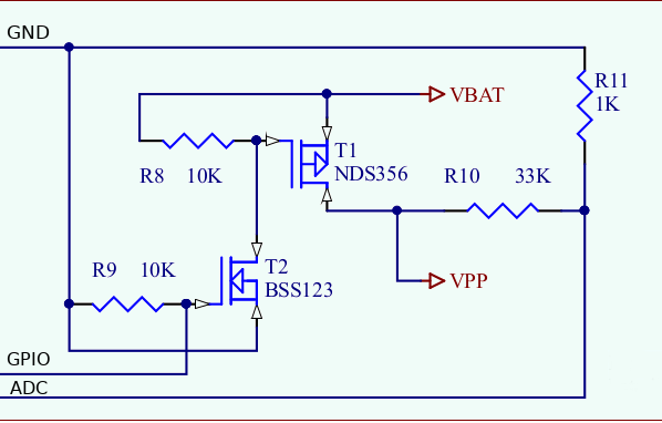
Hello guys, im building my new project, where i want to meassure my battery periocidaly (every 12 hours). I was searching on the internet and i found this scheme.

Image

I want to ask you, if u can recommend me some P MOSFET tranzistor with low rds(on) and with parameters to switch on from MCU gpio pin, which uses 3,3V logic. Battery is operating with 4,2-3,5 Volts.

I want mosfet which will cover all those conditions.

If u have any recommendations, how to improve the scheme or even change it completely so current drain is minimal (or none), let me know please.

Thanks!

Re: MOSFET CHOICE

Posted: Tue Feb 13, 2018 11:09 pm
by iot_guy
Unless your MCU pin is 5 volt tolerant you can't use it directly to switch a P channel MOSFET as for the NMOSFET to be off the gate needs to be pulled up to the battery voltage. Hence the use of a NPN transistor in the diagram (could also have been a N channel MOSFET).

Re: MOSFET CHOICE

Posted: Tue Feb 13, 2018 11:22 pm
by loboris
I'm using NDS356 for P-MOS and you can replace BC547 with N-MOS.

This is the schematics I'm using for years.
Current drain is none when GPIO is low, setting GPIO to high opens the P-MOS.
VBAT can be up to 18V, select the R10/R11 to get the desired voltage.
You can use VPP to power some device (up to 1A), use high current MOSFET (for example FDN302P) for T1 if you need the current up to 2.4 A.

Image

Re: Mosfet choice

Posted: Wed Feb 14, 2018 9:15 am
by Nespressif
Hi guys, what you build would be the same as thishttps://es.aliexpress.com/item/10pcs-lo ... 0.0.aRy6W6? Though I'm doing it for you, of course.

I'd like to know if it's the same or similar, thank you.

Re: Mosfet choice

Posted: Wed Feb 14, 2018 9:41 am
by BuddyCasino
Or use a specialized IC like this one: http://www.ti.com/product/ina226

Re: MOSFET CHOICE

Posted: Wed Feb 14, 2018 2:20 pm
by Azaelyus
Current drain is none when GPIO is low, setting GPIO to high opens the P-MOS.
What does it mean none? Under 1 uA?
VBAT can be up to 18V, select the R10/R11 to get the desired voltage.
Will the circuit work with battery level 4,2 max to 3,5 min and GPIO 3,3V? In case i use NDS356 as P and BSS123 as N MOSFET? Divider will be 10+10K.

Also, the VBAT goes to MCP1700 to stabilize the voltage to 3,3 V for ESP32.

Re: Mosfet choice

Posted: Wed Feb 14, 2018 4:16 pm
by loboris
@Azaelyus

none -> far less than 1 uA.
It should work with any voltage (on VBAT) up to 17V.

I've used this circuit to power the GSM module from LiPo battery, there was no measurable current when switched off (GPIO=0V).

Re: Mosfet choice

Posted: Wed Feb 14, 2018 4:20 pm
by Azaelyus
This is great! :)

Do i need to set the GPIO to pull down or something else?

Also, are there any newer MOSFETs on the market? Farnell etc? Maybe we can get lower RDS(on) (those two have like 6 ohm, which is quite bad). I dont really understand how MOSFETs work, thats why i am asking. :/

Edit: why is R9 grounded? I have seen many scheme where that resistor is placed like this

Image

Re: Mosfet choice

Posted: Wed Feb 14, 2018 6:31 pm
by loboris
R9 is grounded to pull T2 gate low in case GPIO is floating.
There is no need for serial resistor to the MOSFET gate (T2)!

GPIO has to be configured as output.

You can use any P MOSFET with similar characteristics, the RDS will have practically no influence on 2x 10K voltage divider.
NDS356 has RDS ~0.3 Ohm, the mentioned FDN302P has RDS of ~0.06 Ohm.

Re: Mosfet choice

Posted: Wed Feb 14, 2018 7:04 pm
by Azaelyus
Thank you! Great explanation. I will use those two.
P T1 - http://uk.farnell.com/on-semiconductor/ ... ?st=nds356
N T2 - which one of those 3 is the best one?

http://uk.farnell.com/on-semiconductor/ ... ?st=bss123
http://uk.farnell.com/diodes-inc/bss123 ... ?st=bss123
http://uk.farnell.com/nexperia/bss123-2 ... ?st=bss123

EDIT: Do you think my scheme will be working like this?

Image