Micropython as debug shell for ESP32 (and its OLED)

User avatar
HermannSW
Posts: 97
Joined: Fri Oct 27, 2017 6:58 am
Location: Eberbach, Germany
Contact:

Micropython as debug shell for ESP32 (and its OLED)

Postby HermannSW » Mon Oct 30, 2017 8:55 pm

In other thread (see here) I asked how to run built in ROM Basic.
My intent was to use Basic as debug shell for eg. easy testing of pins after soldering.
On Arduinos I use http://bitlash.net/ for that, and for Raspberry Pi Zero I use my Android as Terminal https://www.raspberrypi.org/forums/view ... 6&t=196057 for bash shell.

In the ROM Basic thread WiFive proposed to use Micropython as ESP32 shell instead.
And ESP_Sprite confirmed that ROM Basic would not work with more than one command.

So I wanted to try out Micropython.
Instead of building it myself, I followed most of the steps from this Instructable posting and installed the daily binary:
http://www.instructables.com/id/MicroPy ... ated-SSD1/

I used "~/.arduino15/packages/espressif/esp32/tools/esptool.py" instead of the esptool.py present on my system, because that was for ESP8266 systems and did not work with ESP32.

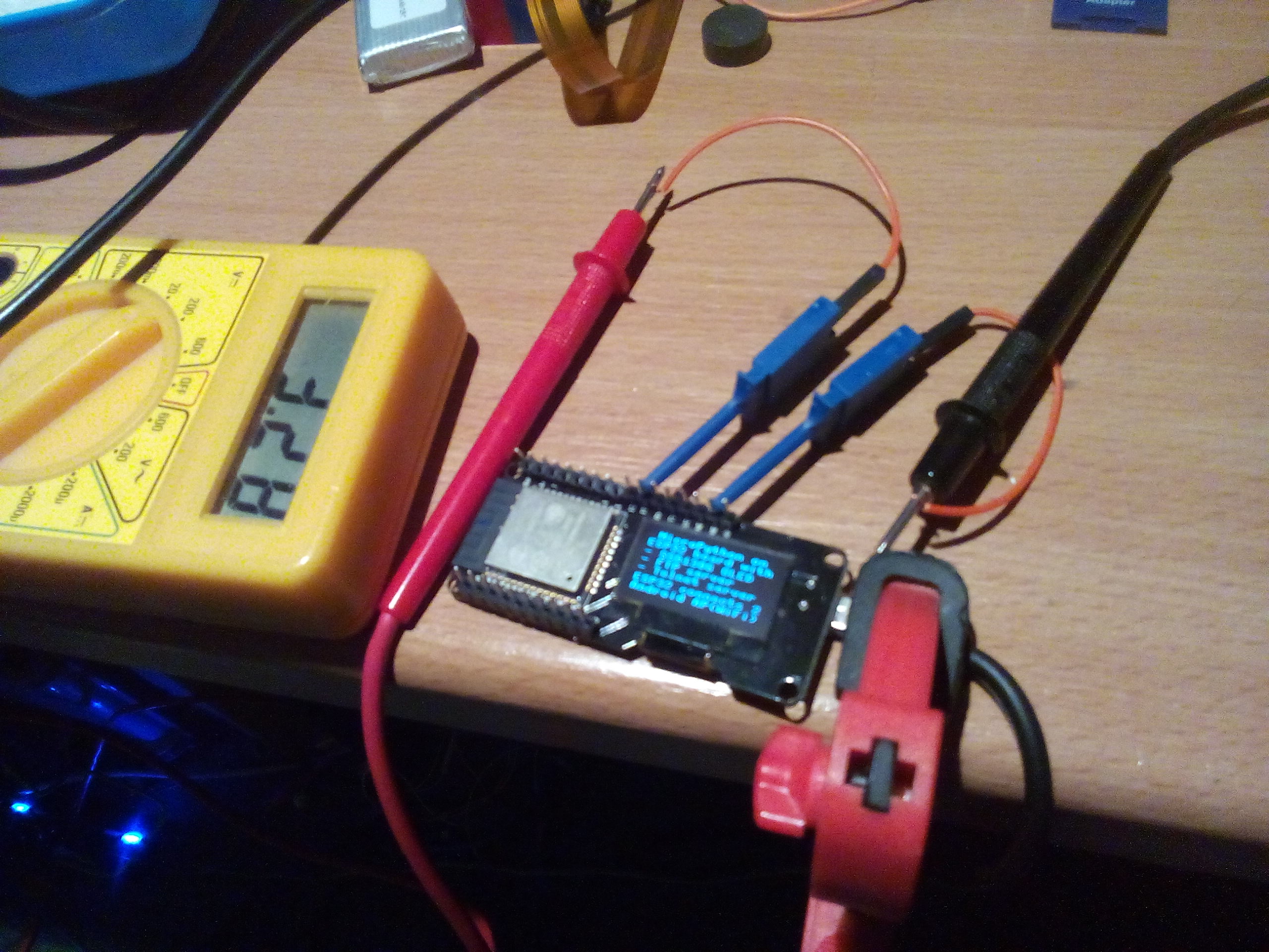
I installed ampy and used that to upload Adafruit "ssd1306.py" to ESP32, and as described in posting that allows to even output to the OLED!
Image

You can copy&paste several lines at once, but all OLED lines together do not work due to some buffer limits, but two parts work.

You can copy&paste this

Code: Select all

import machine, ssd1306
i2c = machine.I2C(scl=machine.Pin(4), sda=machine.Pin(5))
oled = ssd1306.SSD1306_I2C(128, 64, i2c)
and then this

Code: Select all

oled.fill(0) 
oled.text('MicroPython on', 0, 0)
oled.text('an ESP32 with an', 0, 10)
oled.text('attached SSD1306', 0, 20)
oled.text('OLED display', 0, 30)
oled.show()
I typed "help()" and from it I copied these three lines:

Code: Select all

import machine
pin12 = machine.Pin(12, machine.Pin.OUT)
pin12.value(1)
This lighted the LED (with resistor) connected to pin 12 and GND.

Help says that even Wifi can be done with few statements.
So definitely Micropython is much more than what I need for ESP32 debug shell, I will use it !

Hermann.

P.S:
I was not able to get minicom to work with Micropython. I remembered an even easier command, and "screen /dev/ttyUSB0 115200" works perfectly!

P.P.S:
Just learned howto do Arduino IDE Blink sketch in Micropython:

Code: Select all

import machine, time
pin12 = machine.Pin(12, machine.Pin.OUT)
while True:
    pin12.value(1)
    time.sleep(1)
    pin12.value(0)
    time.sleep(1)

User avatar
HermannSW
Posts: 97
Joined: Fri Oct 27, 2017 6:58 am
Location: Eberbach, Germany
Contact:

Re: Micropython as debug shell for ESP32 (and its OLED)

Postby HermannSW » Fri Nov 10, 2017 10:50 am

I wanted to get a wireless ESP32 debug solution and tried Telnet servers in MicroPython for that. Unfortunately there is an issue with "dupterm()" not being implemented in ESP32 MicroPython, see this thread:
https://forum.micropython.org/viewtopic.php?f=18&t=3997

In this thread user loboris pointed to his own MicroPython port for ESP32, with multi-core support, Telnet and FTP server.
I tried the last built, and while MicroPython worked flawlessly, the Telnet server was not enabled.
I asked him for a new build with Telnet server enabled, which he did provide!
https://forum.micropython.org/viewtopic ... 997#p23075
Image

Just to have all in one place here you can find that version (small .zip) I used attached to this posting.
In case you are interested in his full distro and documentation, you can find it here:
https://forum.micropython.org/viewtopic ... 997#p22937

For installing on your ESP32 module you just need working "esptool.py" and modify "esp32/flash.sh" to your needs:

Code: Select all

$ unzip -l MPy_loboris_firmware_latest.zip
Archive:  MPy_loboris_firmware_latest.zip
  Length      Date    Time    Name
---------  ---------- -----   ----
        0  10-14-2017 15:47   esp32/
        0  07-21-2017 15:21   esp32/bootloader/
    19760  11-08-2017 21:06   esp32/bootloader/bootloader.bin
  1258272  11-08-2017 21:06   esp32/MicroPython.bin
    13384  11-08-2017 21:06   esp32/sdkconfig
      403  11-08-2017 21:06   esp32/flash.sh
     3072  11-08-2017 21:06   esp32/partitions_mpy.bin
      144  11-08-2017 21:06   esp32/phy_init_data.bin
---------                     -------
  1295035                     8 files
$ 
After "screen /dev/ttyUSB0 115200" and pressing Reset button on module you see bootup messages and command prompt.

The first I did yesterday evening was to start Telnet server and login to ESP32 via telnet, worked like a charm !
You can see telnet wireless into MicroPython command line, then do interactively a WiFi scan followed by Arduino "Blink" sketch (in micropython):
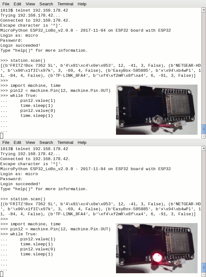
Image

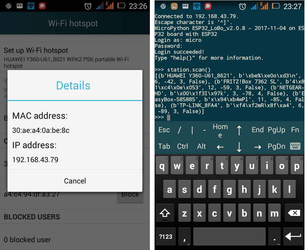
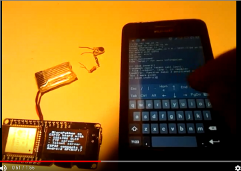
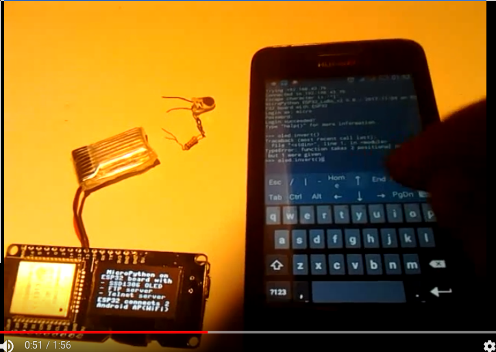
Next I made my Android a wireless Access Point and made ESP32 MicroPython connect to it (left side shows how do determine ESP32s IP address by clicking on mac address, needed for being able to open telnet session to ESP32 with Image app):
Image

Here is a 2min youtube video demonstrating how to work with Android as mobile wireless terminal for ESP32 MicroPython:
https://www.youtube.com/watch?v=8Batb22 ... e=youtu.be
  1. determined ESP32 IP address on Android
  2. opened telnet session to ESP32 in JuiceSSH app
  3. logged in as "micro" user with default password "python"
  4. created a syntax error intentionally by executing "oled.invert()"
  5. enabled JuiceSSH extended keyboard with arrow keys, CTRL, ...
  6. pressed arrow up to get last command, corrected by inserting "1" into parenthesis
  7. now OLED display got inverted
  8. executed "machine.reset()"
  9. ESP32 rebooted and boot messages appeared on OLED display
  10. JuiceSSH telnet session got terminated
  11. opened new telnet session and logged in again
  12. now executed "station.scan()" doing full WiFi scan
  13. all access points found got shown in telnet session
As described typos are not an issue because arrow keys allow to easily access complete MicroPython command line history and modify+execute them.
Image


This is the listing of MicroPython "boot.py" I created and used for enabling OLED display, FTP server and Telnet server (allowing wireless telnet session from Android -- and from laptop, if that is connected to Android AP wireless). It imports modules network, machine, ssd1306, os and time which are available to you. And it defines variables station for WiFi and oled for display output for you:

Code: Select all

# This file is executed on every boot (including wake-boot from deepsleep)
import sys
sys.path[1] = '/flash/lib'

import network
station = network.WLAN(network.STA_IF)
station.active(True)
station.connect("HUAWEI Y360-U61_8621", "verySecret ;-)")

import machine, ssd1306
i2c = machine.I2C(scl=machine.Pin(4), sda=machine.Pin(5))
oled = ssd1306.SSD1306_I2C(128, 64, i2c)

oled.fill(0)
oled.text(' MicroPython on ', 0, 0)
oled.text('ESP32 board with', 0, 9)
oled.text('- SSD1306 OLED  ', 0, 19)
oled.text('- FTP server    ', 0, 28)
oled.text('- Telnet server ', 0, 37)
oled.text('ESP32 connects 2', 0, 48)
oled.text('Android AP(WiFi)', 0, 57)
oled.show()

network.telnet.start()
network.ftp.start()

import os, time

How do you get this onto your MicroPython?
After you had installed MicroPython the first time and connected via eg. "screen /dev/ttyUSB0", just execute these two commands interactively:

Code: Select all

import network
network.ftp.start()
Then ftp into your ESP32, after "cd flash" you can do "get boot.py" to download the version present, then modify it to your needs (like I did above) and put onto ESP32 with "put boot.py". You have to do this once only, since from next boot on Telnet and FTP server will be started automatically! This MicroPython mobile wireless debug+dev solution is self contained, no tools like ampy needed anymore for file upload/download (although you still can use them if you want).

Hermann.

P.S:
I just booted ESP32 and Android was not enabled as wireless AP.
ESP32 booted flawless.
Then I enabled wireless AP on Android, and a few seconds later the ESP32 got shown as connected.
So order of actions on ESP32 and Android is not important.

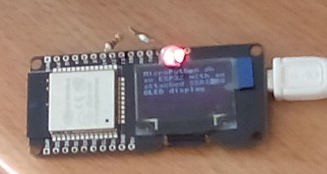
As hands on exercise for you, after installation as described above.
Do copy+paste these lines (including the last three empty lines) into your MicroPython session:

Code: Select all

while True:
oled.invert(1)
time.sleep(1)
oled.invert(0)
time.sleep(1)


Attachments
MPy_loboris_firmware_latest.zip
(756.61 KiB) Downloaded 1015 times

User avatar
HermannSW
Posts: 97
Joined: Fri Oct 27, 2017 6:58 am
Location: Eberbach, Germany
Contact:

Re: Micropython as debug shell for ESP32 (and its OLED)

Postby HermannSW » Sun Jan 07, 2018 7:07 pm

I did solder headers to one of my ESP32 modules and used the still flashed Micropython to verify the pins:
http://forum.arduino.cc/index.php?topic ... msg3553490

Only pins left where I need to find out how to test are the non-numbered pins SVP, S1, CM, S0, CL, SND, SVN, RX, TX, all other pins have been verified as good.

I did solder the headers to control 12V motors. Although I plan to use Arduino IDE for the final application, I found out how to do PWM with Micropython (the 8266 doc I found is good enough for ESP32):
https://docs.micropython.org/en/latest/ ... l/pwm.html

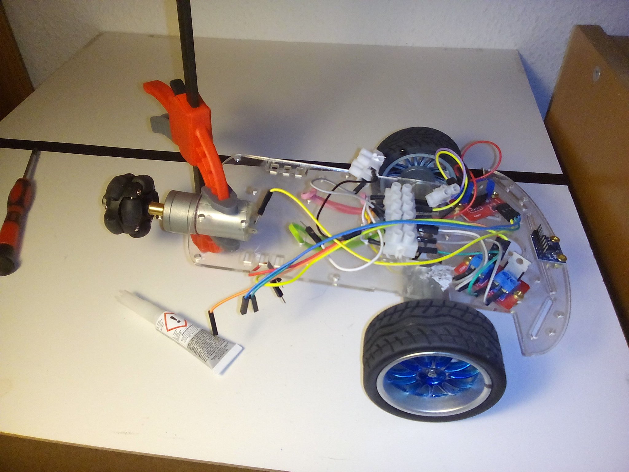
So next step is cabling module to robot and then PWM testing with Micropython first ...
Image

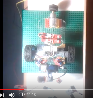
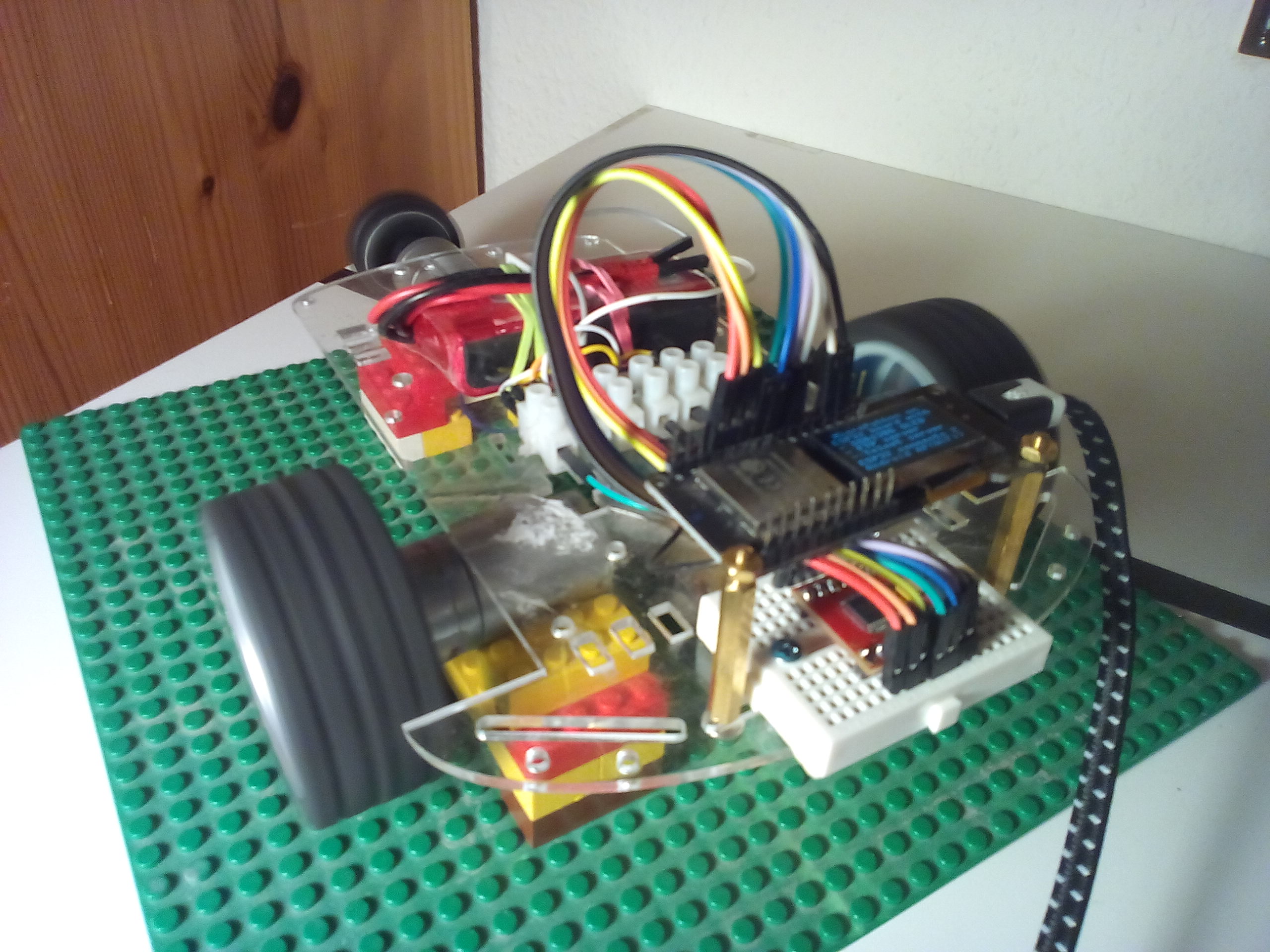
Will be interesting, it is the first of my robots with a dedicated steering omni wheel motor ...
Image

User avatar
HermannSW
Posts: 97
Joined: Fri Oct 27, 2017 6:58 am
Location: Eberbach, Germany
Contact:

Re: Micropython as debug shell for ESP32 (and its OLED)

Postby HermannSW » Mon Jan 08, 2018 11:57 pm

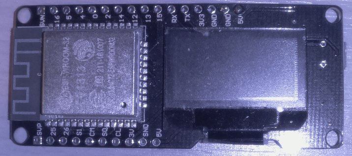
Update on pin verification, see pin naming for my ESP32 module in photo detail below.
Via google search I did find out that RX is 3 and TX is 1, which I verified as above,
Then I investigated all GPIO numbers N in 0-31 [by executing "pin = machine.Pin(N, machine.Pin.OUT)" ]:
  • 20,24,28-31 invalid
  • 9,10,17-19,21-23,27 ?
  • 6-8,11 hangs ESP32
  • 0,2,4,5,12-16,25,26 see photo
  • 1 TX
  • 3 RX
Besides RX and TX I was not able to identify pin number of any of these pins:

Code: Select all

SVP, S1, CM, S0, CL, SND, SVN
Anyway, was able to verify soldering is good for 19 of 26 module pins.

Image
Last edited by HermannSW on Tue Jan 09, 2018 1:31 am, edited 1 time in total.


User avatar
HermannSW
Posts: 97
Joined: Fri Oct 27, 2017 6:58 am
Location: Eberbach, Germany
Contact:

Re: Micropython as debug shell for ESP32 (and its OLED)

Postby HermannSW » Mon Jan 15, 2018 9:39 pm

Thank you so much!

The "Flash ..." GPIO labelling for 6-8 and 11 might be an explanation on ESP32 hang when I set any of those to OUTPUT as in previous posting.

"SND" being "GND" is funny, and yes, I measure 0V on that pin.

GPIO 36 and GPIO39 are interesting, cannot be OUTPUT:

Code: Select all

>>> pin = machine.Pin(36, machine.Pin.OUT)
Traceback (most recent call last):
  File "<stdin>", line 1, in <module>
ValueError: pin can only be input
>>> pin = machine.Pin(39, machine.Pin.OUT)
Traceback (most recent call last):
  File "<stdin>", line 1, in <module>
ValueError: pin can only be input
>>>
But they work and are really the pins labelled SVP and SVN on my module:

Code: Select all

>>> pin = machine.Pin(36, machine.Pin.IN)
>>> print(pin.value())
0
>>> print(pin.value())
1
>>> pin = machine.Pin(39, machine.Pin.IN)
>>> print(pin.value())
0
>>> print(pin.value())
1
>>> 
The 1 values appeared after I connected the GPIO pins with 3V pin.

Summary:
Now verified 22/26 GPIO pins, open only verification for GPIOs 6-8 and 11.


P.S:
I used MicroPython for first wireless test of jacked new steering omni wheel robot, details here:
https://forum.arduino.cc/index.php?topi ... msg3565721
Image
Last edited by HermannSW on Mon Jan 15, 2018 11:39 pm, edited 1 time in total.

User avatar
HermannSW
Posts: 97
Joined: Fri Oct 27, 2017 6:58 am
Location: Eberbach, Germany
Contact:

Re: Micropython as debug shell for ESP32 (and its OLED)

Postby HermannSW » Mon Jan 15, 2018 11:31 pm

.
Last edited by HermannSW on Mon Jan 15, 2018 11:42 pm, edited 1 time in total.


User avatar
HermannSW
Posts: 97
Joined: Fri Oct 27, 2017 6:58 am
Location: Eberbach, Germany
Contact:

Re: Micropython as debug shell for ESP32 (and its OLED)

Postby HermannSW » Wed Jan 17, 2018 7:57 pm

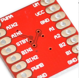
I went a step further after I exchanged the two unidirectional MOSFETs with a TB6612FNG motor driver, see bottom photo. Just saw that these modules cost <1$ with free shipping today.
Image

So this is kind of another level of debugging, not single pins anymore, but motor functionality.

After I learned how to define functions (first interactively), I added some motor stuff to previous boot.py and FTPed it onto the ESP32. Quite handy, now "stby.value(1)" enables the module, "pwma.duty(1023)" sets speed of the two back motors to maximum and "forward()" does what it should. "stop()" is the slow stopping version, use "brake()" for immediate stop. "left()"/"right()" are for the steering motor as well as "sstop()"/"sbrake()".

This is the addition diff:

Code: Select all

$ diff boot.py.orig boot.py
28a29,91
> pwma = machine.PWM(machine.Pin(15))
> ain2 = machine.Pin(13, machine.Pin.OUT)
> ain1 = machine.Pin(12, machine.Pin.OUT)
> stby = machine.Pin(14, machine.Pin.OUT)
> bin1 = machine.Pin( 2, machine.Pin.OUT)
> bin2 = machine.Pin( 0, machine.Pin.OUT)
> pwmb = machine.PWM(machine.Pin(4))
> 
> stby.value(0)
> 
> def forward():
>     ain1.value(1)
>     ain2.value(0)
>     
>     
> 
> def backward():
>     ain2.value(1)
>     ain1.value(0)
>     
>     
> 
> def stop():
>     ain1.value(0)
>     ain2.value(0)
>     
>     
> 
> def brake():
>     ain1.value(1)
>     ain2.value(1)
>     
>     
> 
> 
> def left():
>     bin1.value(1)
>     bin2.value(0)
>     
>     
> 
> def right():
>     bin1.value(0)
>     bin2.value(1)
>         
> 
> 
> def sstop():
>     bin1.value(0)
>     bin2.value(0)
>     
>     
> 
> def sbrake():
>     bin1.value(1)
>     bin2.value(1)
>     
>     
> stop()
> sstop()
> pwma.value(0)
> pwmb.value(0)
> 
$ 

There is only one issue I don't understand. When everything works, and I do "stop()", "sstop()" and "stby.value(0)" followed by "machine.reset()" ESP32 display gets blank, steering motor rotates, and no reboot happens. Even if I disconnect the 11.4V 3S Lipo nothing happens. I have to power the ESP32 off and on to get it started successfully. Then I can reconnect the Lipo as well. I am not sure if that is a Micropython issue, or a "feature" of the motor driver.

Image

P.S:
Learned from a friend how to get a listing of all stuff I defined in boot.py or interactively:

Code: Select all

>>> globals()
{'bin2': Pin(0), 'time': <module 'utime'>, 'forward': <function forward at 0x3ffe6600>, 'sys': <module 'sys'>, '__name__': '__main__', 'os': <module 'uos'>, 'brake': <function brake at 0x3ffe6660>, 'network': <module 'network'>, 'backward': <function backward at 0x3ffe6610>, 'station': <WLAN>, 'ssd1306': <module 'ssd1306'>, 'stop': <function stop at 0x3ffe6650>, 'pwmb': PWM(4, freq=5000, duty=1023), 'pwma': PWM(15, freq=5000, duty=1023), 'left': <function left at 0x3ffe67e0>, 'sbrake': <function sbrake at 0x3ffe68d0>, 'oled': <SSD1306_I2C object at 3ffe6190>, 'ain2': Pin(13), 'ain1': Pin(12), 'sstop': <function sstop at 0x3ffe6890>, 'right': <function right at 0x3ffe6880>, 'i2c': I2C(Port=0, Mode=MASTER, speed=100000Hz, sda=GPIO_NUM_5, scl=GPIO_NUM_4), 'stby': Pin(14), 'machine': <module 'umachine'>, 'bin1': Pin(2)}
>>> 

User avatar
HermannSW
Posts: 97
Joined: Fri Oct 27, 2017 6:58 am
Location: Eberbach, Germany
Contact:

Re: Micropython as debug shell for ESP32 (and its OLED)

Postby HermannSW » Thu Jan 18, 2018 1:56 am

HermannSW wrote:I went a step further after I exchanged the two unidirectional MOSFETs with a TB6612FNG motor driver, see bottom photo. Just saw that these modules cost <1$ with free shipping today.
Image

So this is kind of another level of debugging, not single pins anymore, but motor functionality.

After I learned how to define functions (first interactively), I added some motor stuff to previous boot.py and FTPed it onto the ESP32. Quite handy, now "stby.value(1)" enables the module, "pwma.duty(1023)" sets speed of the two back motors to maximum and "forward()" does what it should. "stop()" is the slow stopping version, use "brake()" for immediate stop. "left()"/"right()" are for the steering motor as well as "sstop()"/"sbrake()".

This is the addition diff:

Code: Select all

$ diff boot.py.orig boot.py
28a29,91
> pwma = machine.PWM(machine.Pin(15))
> ain2 = machine.Pin(13, machine.Pin.OUT)
> ain1 = machine.Pin(12, machine.Pin.OUT)
> stby = machine.Pin(14, machine.Pin.OUT)
> bin1 = machine.Pin( 2, machine.Pin.OUT)
> bin2 = machine.Pin( 0, machine.Pin.OUT)
> pwmb = machine.PWM(machine.Pin(4))
> 
> stby.value(0)
> 
> def forward():
>     ain1.value(1)
>     ain2.value(0)
>     
>     
> 
> def backward():
>     ain2.value(1)
>     ain1.value(0)
>     
>     
> 
> def stop():
>     ain1.value(0)
>     ain2.value(0)
>     
>     
> 
> def brake():
>     ain1.value(1)
>     ain2.value(1)
>     
>     
> 
> 
> def left():
>     bin1.value(1)
>     bin2.value(0)
>     
>     
> 
> def right():
>     bin1.value(0)
>     bin2.value(1)
>         
> 
> 
> def sstop():
>     bin1.value(0)
>     bin2.value(0)
>     
>     
> 
> def sbrake():
>     bin1.value(1)
>     bin2.value(1)
>     
>     
> stop()
> sstop()
> pwma.value(0)
> pwmb.value(0)
> 
$ 

There is only one issue I don't understand. When everything works, and I do "stop()", "sstop()" and "stby.value(0)" followed by "machine.reset()" ESP32 display gets blank, steering motor rotates, and no reboot happens. Even if I disconnect the 11.4V 3S Lipo nothing happens. I have to power the ESP32 off and on to get it started successfully. Then I can reconnect the Lipo as well. I am not sure if that is a Micropython issue, or a "feature" of the motor driver.

Image

P.S:
Learned from a friend how to get a listing of all stuff I defined in boot.py or interactively:

Code: Select all

>>> globals()
{'bin2': Pin(0), 'time': <module 'utime'>, 'forward': <function forward at 0x3ffe6600>, 'sys': <module 'sys'>, '__name__': '__main__', 'os': <module 'uos'>, 'brake': <function brake at 0x3ffe6660>, 'network': <module 'network'>, 'backward': <function backward at 0x3ffe6610>, 'station': <WLAN>, 'ssd1306': <module 'ssd1306'>, 'stop': <function stop at 0x3ffe6650>, 'pwmb': PWM(4, freq=5000, duty=1023), 'pwma': PWM(15, freq=5000, duty=1023), 'left': <function left at 0x3ffe67e0>, 'sbrake': <function sbrake at 0x3ffe68d0>, 'oled': <SSD1306_I2C object at 3ffe6190>, 'ain2': Pin(13), 'ain1': Pin(12), 'sstop': <function sstop at 0x3ffe6890>, 'right': <function right at 0x3ffe6880>, 'i2c': I2C(Port=0, Mode=MASTER, speed=100000Hz, sda=GPIO_NUM_5, scl=GPIO_NUM_4), 'stby': Pin(14), 'machine': <module 'umachine'>, 'bin1': Pin(2)}
>>> 

Who is online

Users browsing this forum: Bing [Bot] and 114 guests