Page 1 of 2
Searching IO0 Pin
Posted: Tue Jul 18, 2017 6:30 pm
by mattismyo
Can somebody tell me please, where the IO0 Pin should be?

Re: Searching IO0 Pin
Posted: Tue Jul 18, 2017 7:05 pm
by kolban
Do you have a link to the source of the board? Maybe the manufacturers page?
Re: Searching IO0 Pin
Posted: Tue Jul 18, 2017 7:10 pm
by mattismyo
Re: Searching IO0 Pin
Posted: Tue Jul 18, 2017 7:24 pm
by loboris
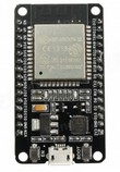
BOOT button is usually connected to GPIO0 and EN switch to CHIP_PU/Chip Enable/EN
Re: Searching IO0 Pin
Posted: Tue Jul 18, 2017 8:10 pm
by mattismyo
Yes, i can see this here

But still can't find out, where IO0 should be. Also tried to follow the wiring, but without success.
Re: Searching IO0 Pin
Posted: Tue Jul 18, 2017 9:04 pm
by WiFive
There is no header pin for GPIO 0 and 6-11 (flash pins)
Re: Searching IO0 Pin
Posted: Tue Jul 18, 2017 9:08 pm
by mattismyo
I want to enter download mode with GPIO 2 by connecting it to GPIO 0. So this is not possible? Or is there another way to do so?
Re: Searching IO0 Pin
Posted: Tue Jul 18, 2017 10:49 pm
by kolban
There may not be a header pin for GPIO 0 on that board, but there are on others including Espressif's module. See:
https://dl.espressif.com/dl/schematics/ ... ard-v2.jpg
6th pin from the top right.
Re: Searching IO0 Pin
Posted: Wed Jul 19, 2017 5:04 am
by samsam
If the schematic of your module is the same as the one you've posted, then you can solder one jumper wire on the pad of the BOOT button @ the pad that is connected to pad 25 - IO0 of the ESP-WROOM-32 module (which is on the picture you posted first - on the right side the bottom one). The other pad of the BOOT button goes to the GND..
Take in mind that the schematic that you've posted maybe is not exact what your board is - on mine board there is 470 ohm resistor between the BOOT button and the IO0 - so check first with multimeter, then if there is some extra resistor in between deside if it still works for your case or not, but the pad of the button is the easiest place you could still solder without serious risk to damage the board

Re: Searching IO0 Pin
Posted: Wed Jul 19, 2017 5:48 pm
by samsam
mattismyo wrote:I want to enter download mode with GPIO 2 by connecting it to GPIO 0. So this is not possible? Or is there another way to do so?
Can you elaborate a little more what and how you trying, because I guess you could be on the wrong track:
In order to be in boot download mode both IO0 and IO2 should be low (i.e. grounded). IO2 is already low, because there is 10k pull down resistor, but IO0 is high because is pulled up also with 10k. Just connecting both together will give you 1.65V or half of the supplied voltage if is different than 3.3V, so you'll stuck in the middle of nowhere: as per the specs 5.1Absolute Maximum Ratings: to be consider IO signal high it need to be Vih>0.75Vio and to be low Vil<0.25Vio ...

I doubt (if this was your intent) anybody here could bet in what mode the mcu will boot


