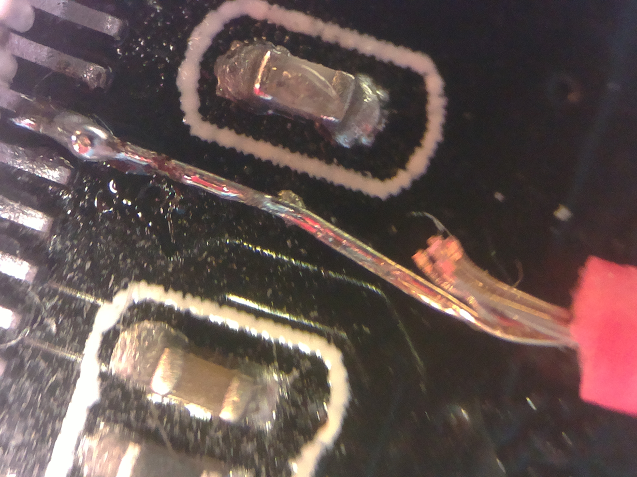
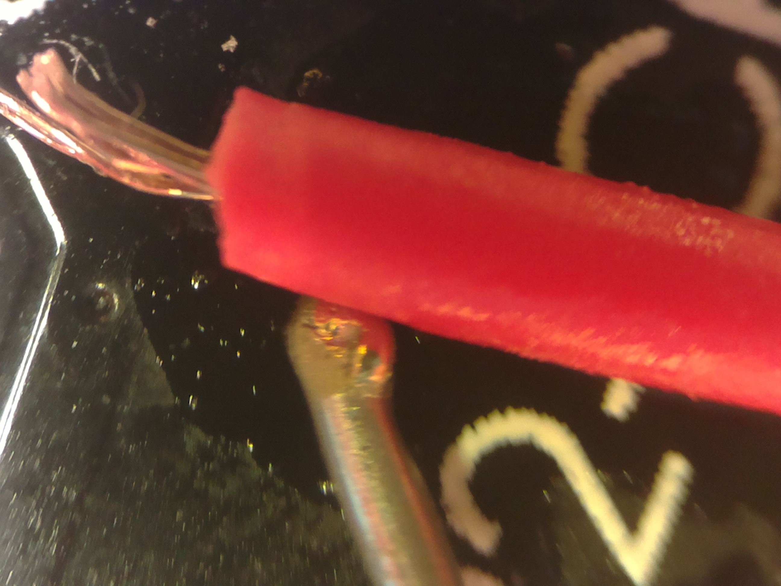
ESP32-CAM ov2640 exposure control/FREX mode

User avatar
HermannSW
Posts: 97
Joined: Fri Oct 27, 2017 6:58 am
Location: Eberbach, Germany
Contact:

ESP32-CAM ov2640 exposure control/FREX mode

Postby HermannSW » Fri Jun 21, 2019 12:54 pm

I recently built a global external shutter for (ov5647 sensor) Raspberry v1 camera:
https://github.com/Hermann-SW/Raspberry ... al_shutter

Since ov2640 sensor is a predecessor of ov5647 and has FREX mode as well (that enables starting accumulation of all sensor lines at the same time) I wanted to try to get my ESP32-CAM modules do global external shutter videos as well.

I am using CameraWebServer.ino Arduino sample sketch, and the GUI exposed by that looks nice in the browser.
As first step I wanted to get a "normal" frame with big rolling shutter effect.
Because of exposure time much too high, I disabled "AEC SENSOR".
Immediately new control "Exposure" appeared with range 0..1200.
I did power a mini drone propeller nearly minimally (with 0.13V instead of 3.7V) and got a very slow rotation.
Because the Exposure selection did not show exact values, I did set to 0 and then pressed 15 times "arrow right" key.
So exposure is likely set to 15 (multiple of single line time exposure).
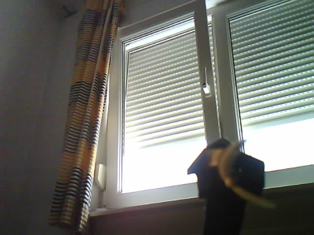
This is a sample frame with quite some rolling shutter effect captured for the propeller:
Image


Next step is to look through CameraWebServer implementation on how to add enabling FREX mode.
For ov5647 it was just writing three I2C registers to get global reset mode enabled:
https://github.com/Hermann-SW/Raspberry ... id_ges#L22


Just as an example for global external shutter multiple exposure frame captured with Raspberry v1 camera:
This is a 9000eps frame (exposures per second) with strobe pulse length 8.33µs.
The 8mm long airgun pellet flies with 96.9m/s(!) through two 5000lm leds (at bottom and top):
https://github.com/Hermann-SW/Raspberry ... nt-9000eps
Image

User avatar
HermannSW
Posts: 97
Joined: Fri Oct 27, 2017 6:58 am
Location: Eberbach, Germany
Contact:

Re: ESP32-CAM ov2640 exposure control/FREX mode

Postby HermannSW » Sat Jun 22, 2019 6:05 pm

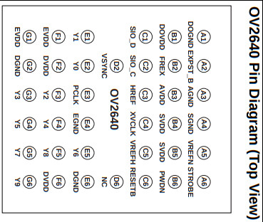
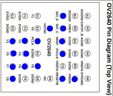
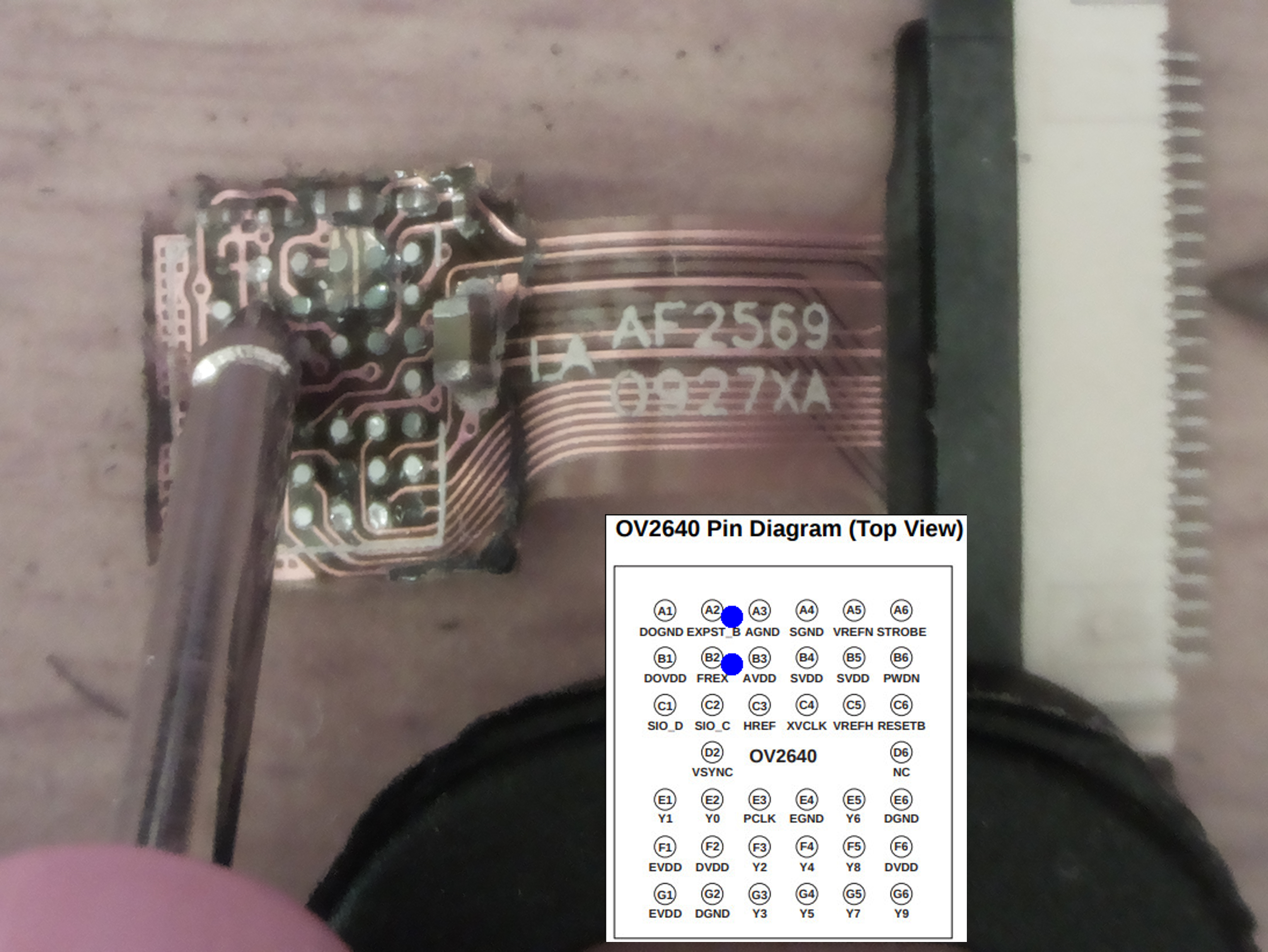
Unlike ov5647 sensor that allows to enter FREX mode either via I2C command (which I did for my global external shutter work) or via pin signalling, ov2640 sensor only allows to enter FREX mode via pin signalling. The interesting pins for entering FREX mode are A2 (EXPST_B) and B2 (FREX), from ov2640 datasheet:
https://datasheetspdf.com/pdf-file/5488 ... s/OV2640/1
Image


According the datasheet there are 38 pins on the sensor, and the connector cable provides 24 lines, 21 of those are connected.

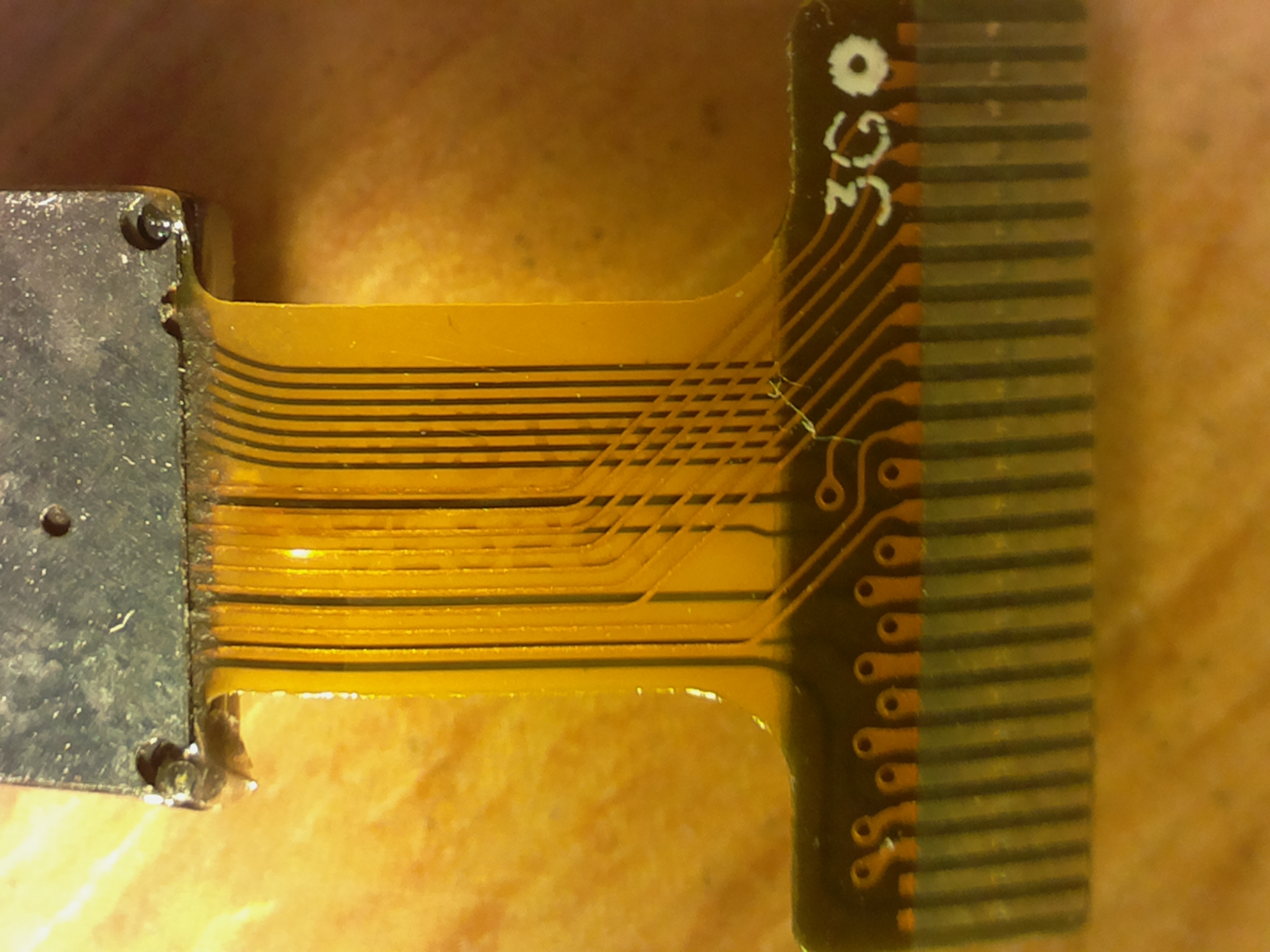
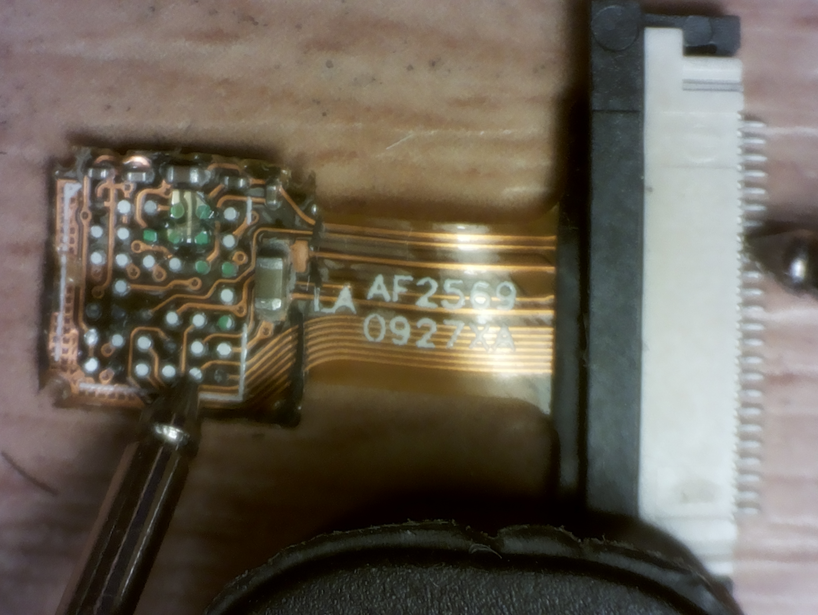
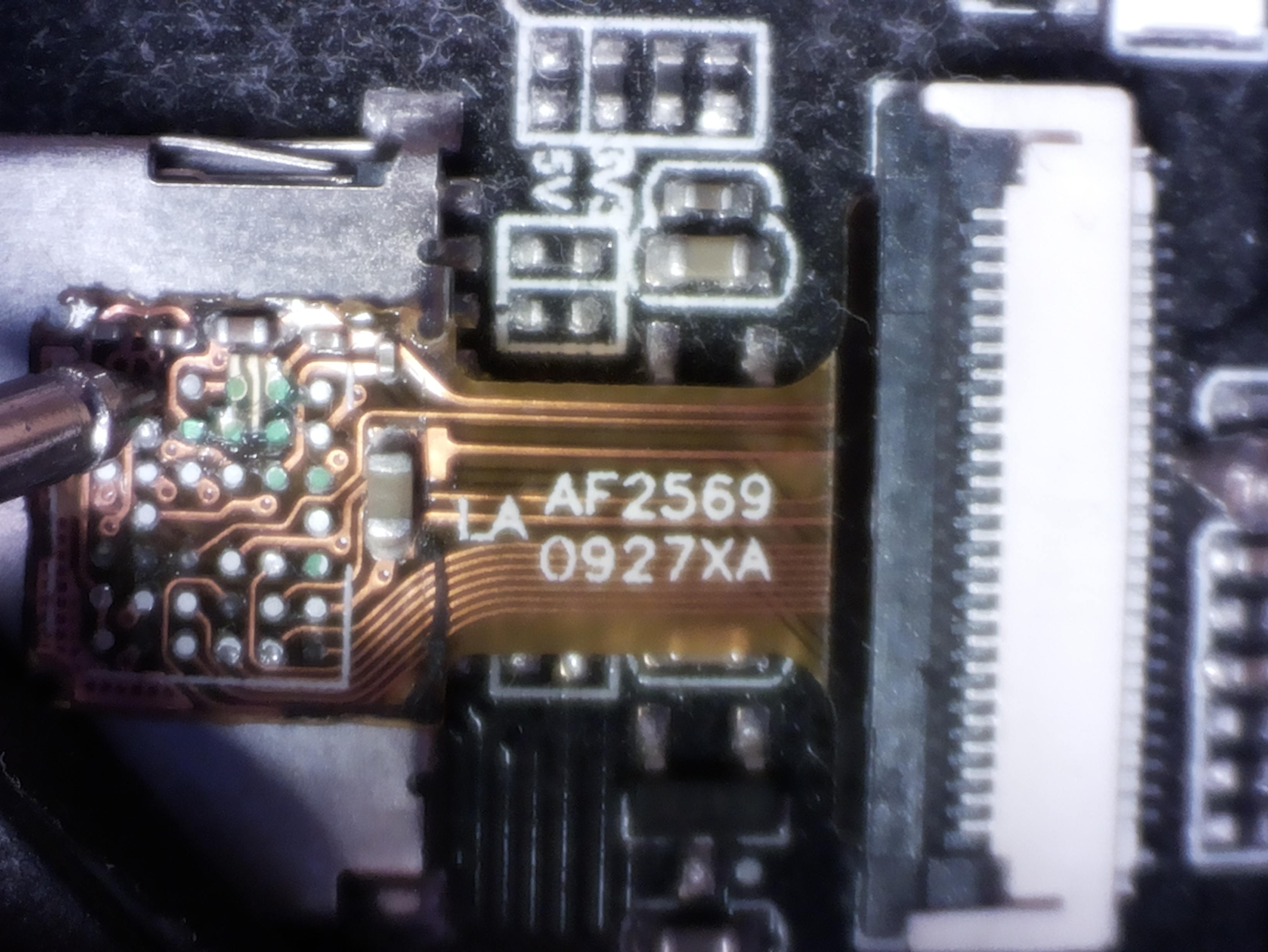
So I wanted to see which 21 pins get exposed on the connector cable, and whether probably A2 and B2 are among them. First I did a 2MP v1 camera photo that gives quite some details for the sensor backside cable connections:
Image


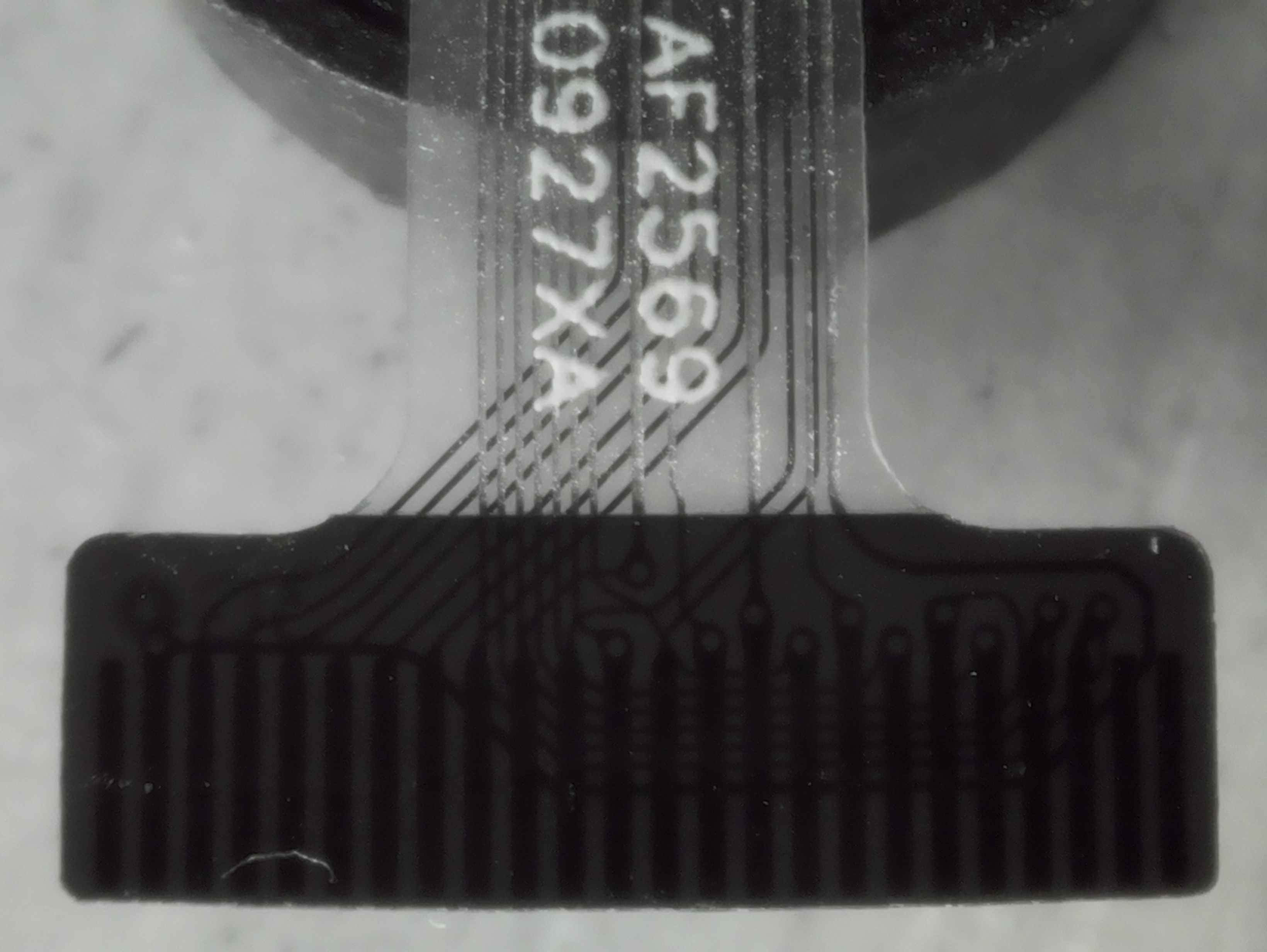
Unfortunately the other side of the connector cable is painted black and did not allow to inspect where the fore side connections of connector cable end. In thread "Raspberry no IR-filter camera see-through images"
https://www.raspberrypi.org/forums/view ... 3&t=243293

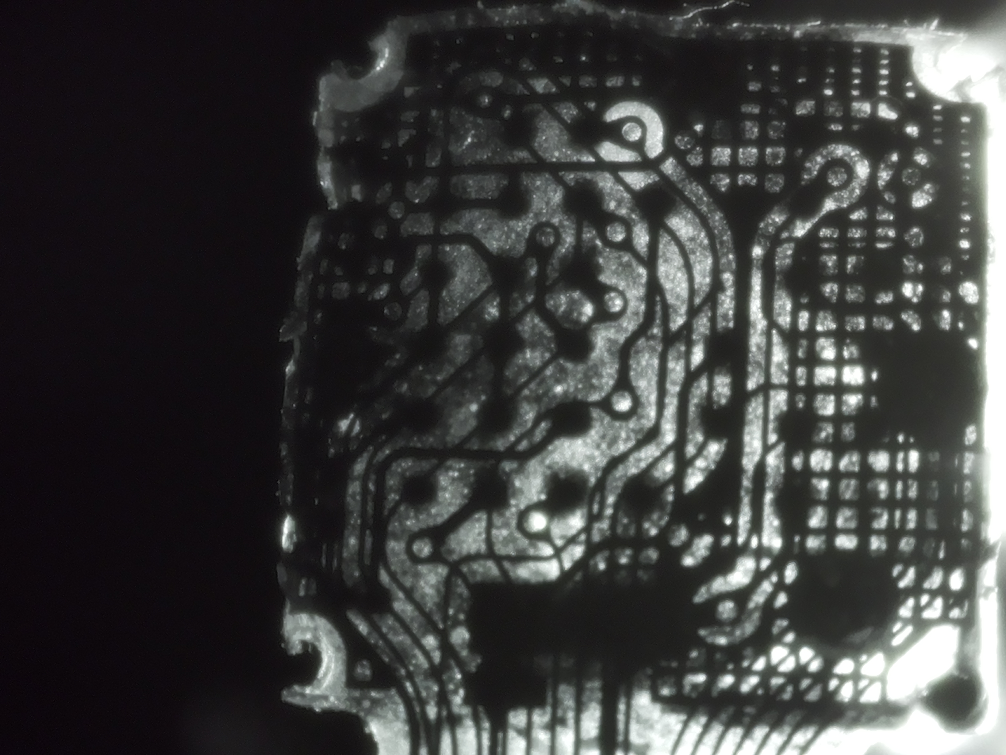
I describe how to use infrared light only photo in order to "see-through" the black colored part of the connector. Now it is relatively easy to identify which fore side cable is connected to which of the 24 connector cable pins (right click and zoom 2MP photo to 100% display):
Image


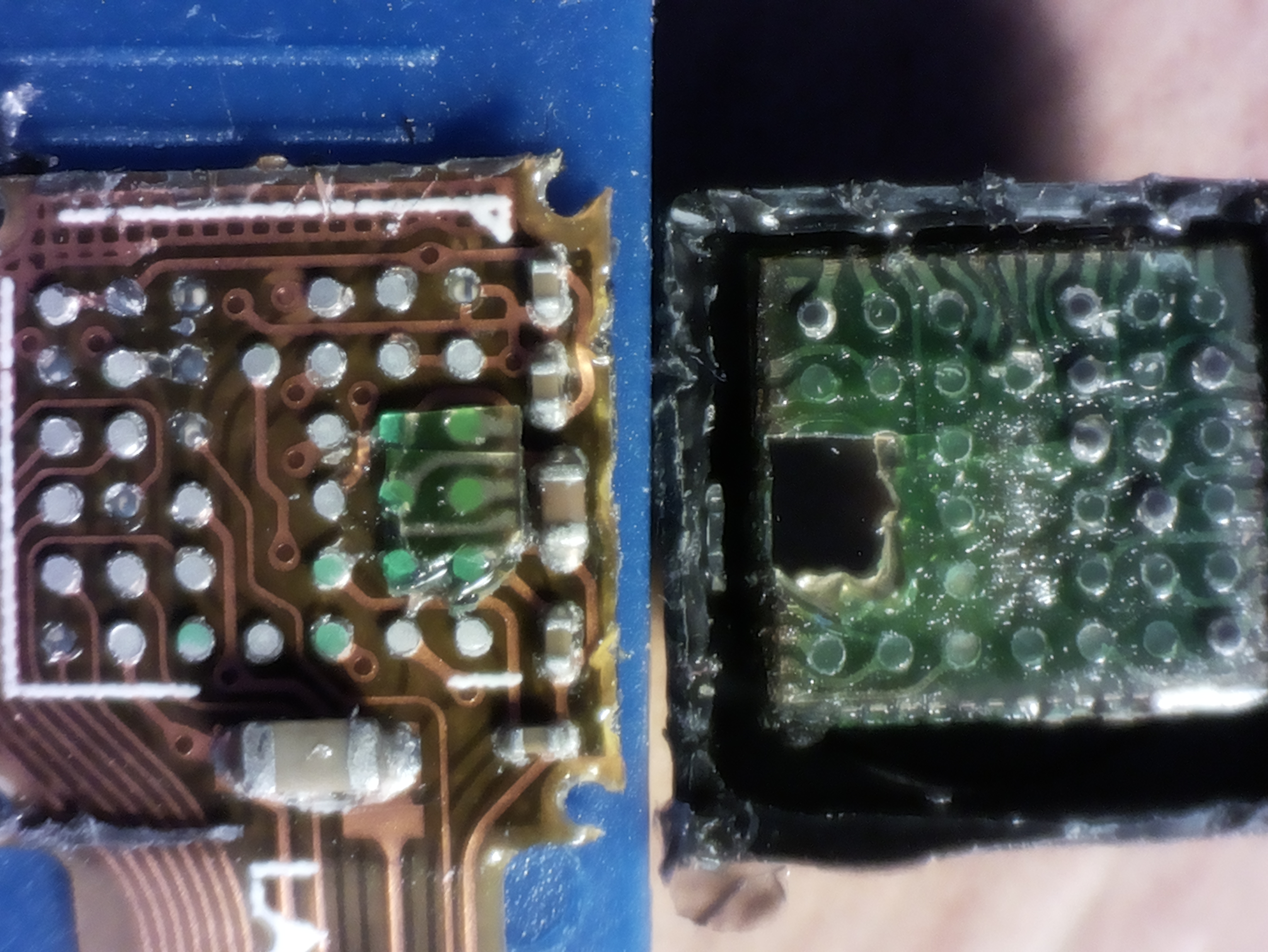
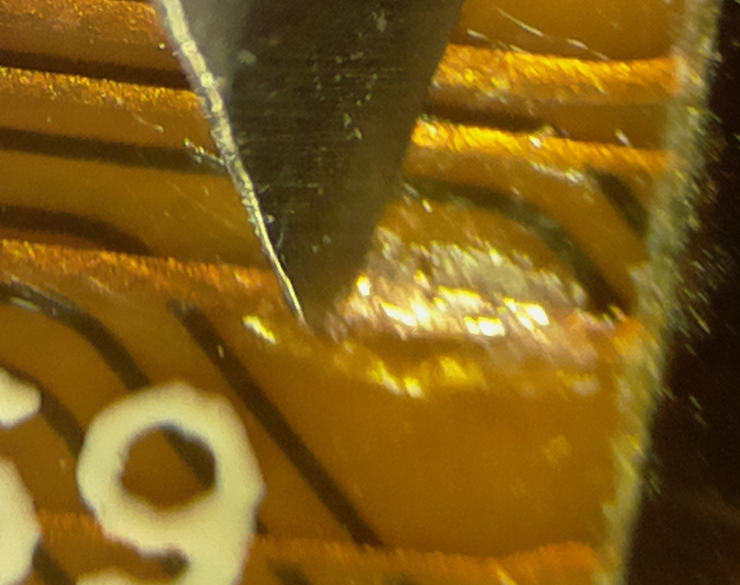
Now that the connections of connector cables and connector pins are known, it is needed to see which of the 38 pins is connected to the 21 cables on connector cable fore and back side. Before I opened the sensor I did order a new replacement ov2640 sensor, and then I did open it with a sharp thin knife:
Image


For comparison the pins from datasheet again:
Image


This is just a snapshot of new results sofar, work in progress ...

P.S:
From "~/.arduino15/packages/esp32/hardware/esp32/1.0.2/libraries/ESP32/examples/Camera/CameraWebServer/camera_pins.h" these 16 pins seem to be among the 21 pins:

Code: Select all

#elif defined(CAMERA_MODEL_AI_THINKER)
#define PWDN_GPIO_NUM     32
#define RESET_GPIO_NUM    -1
#define XCLK_GPIO_NUM      0
#define SIOD_GPIO_NUM     26
#define SIOC_GPIO_NUM     27

#define Y9_GPIO_NUM       35
#define Y8_GPIO_NUM       34
#define Y7_GPIO_NUM       39
#define Y6_GPIO_NUM       36
#define Y5_GPIO_NUM       21
#define Y4_GPIO_NUM       19
#define Y3_GPIO_NUM       18
#define Y2_GPIO_NUM        5
#define VSYNC_GPIO_NUM    25
#define HREF_GPIO_NUM     23
#define PCLK_GPIO_NUM     22

#else

User avatar
HermannSW
Posts: 97
Joined: Fri Oct 27, 2017 6:58 am
Location: Eberbach, Germany
Contact:

Re: ESP32-CAM ov2640 exposure control/FREX mode

Postby HermannSW » Sat Jun 22, 2019 7:26 pm

This are the 16 pins from previous P.S marked in datasheet diagram:
Image


I did remove a metallic plate on the other side of the connector. Grey glue parts remained. Again I did an IR light see-through image, this time with 48-led IR light directly behind the connector -- not sure whether this will help to get the information on pin-connections:
Image

User avatar
HermannSW
Posts: 97
Joined: Fri Oct 27, 2017 6:58 am
Location: Eberbach, Germany
Contact:

Re: ESP32-CAM ov2640 exposure control/FREX mode

Postby HermannSW » Sun Jun 23, 2019 12:08 am

In order to verify visually determined sensor pin to connector pin connections it is necessary to use ohmmeter.
The connector pins are so small that it is really difficult to hit them.
Luckily I had a spare 24-line cable mount.
I fixated that to desk with a one-hnded clamp.
Then I brought Raspberry camera with 2MP mode 1 in place above that so that all fills just the HDMI monitor view.
Then I could pick eg. Y7 (left) and the corresponding pin of connector mount (right) and ohmmeter shows near 0Ω.
In fact it is not that easy to hit a single pin on the right, but get in space between two neighboring pins is easy.
Measuring between pins i-1|i and later between pins i|i+1 allows verification for pin i.
I did try with 2.5 dpt. glasses I use for soldering, but that did not work.
Now Raspberry camera allows to do the verifications by looking onto HDMI monitor(!) the whole time:
Image


P.S:
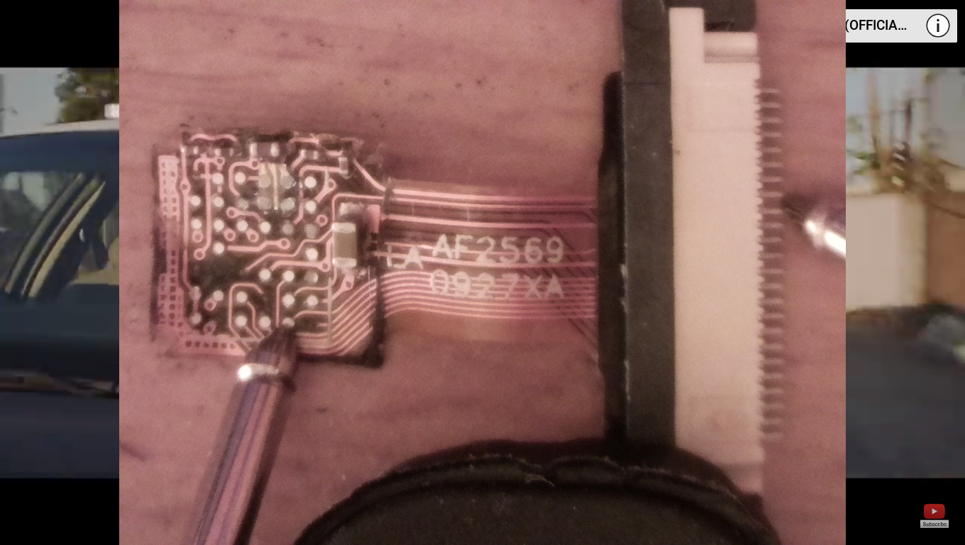
At daylight maginification works without additional light, and with less reflections.
At HDMI monitor borders youtube music video can be seen (screenshot taken with raspi2png):
Image

User avatar
HermannSW
Posts: 97
Joined: Fri Oct 27, 2017 6:58 am
Location: Eberbach, Germany
Contact:

Re: ESP32-CAM ov2640 exposure control/FREX mode

Postby HermannSW » Sun Jun 23, 2019 9:33 am

I was not sure whether A2 and B2 were exposed to connector pins, could be, could be not.

I started to verify G5, G6, E5 and G4 by looking up where the pin should be based on black see-through photo, and then measuring near 0Ω on ohmmeter. It turned out not to be difficult to just select one of the 24 connector pins only, no need to go between two neighboring pins. And it turned out to be easy to firmly connect to sensor pin on left side and keep there by just putting a little pressure from top. It took some time though to get used to looking at HDMI monitor only and not to connector cable on left side.

Next I wanted to search for A2 and B2 connections by going through all the 24 pins on the right side. First I revisited G5 and did a "search" by selecting one pin on the right after the other, starting with top pin 1. Of course I found pin 9 on the right as the matching pin to G5.

Then I started with B2 (the FREX pin is the most important) and was really happy to find it connected to pin 10 on the right. I found a matching pin on the right for A2 as well, to my surprise it was pin 10 as well:
Image


Now does A2 and B2 being connected allow for what I want to do?

On page 4 of datasheet section "Frame Exposure Mode Timing"
https://datasheetspdf.com/pdf-file/5488 ... s/OV2640/1
starts with:
The OV2640 supports frame exposure mode. Typically,
the frame exposure mode must work with the aid of an
external shutter.
That is fine for me, I have built my own (20$) external shutter for the global external shutter work with Raspberry v1 camera:
https://github.com/Hermann-SW/Raspberry ... al-shutter

The next sentences basically say that what I want will NOT DIRECTLY work, BECAUSE A2 and B2 are connected:
The frame exposure pin, FREX (pin B2), is the frame
exposure mode enable pin and the EXPST_B pin (pin A2)
serves as the sensor's exposure start trigger. When the
external master device asserts the FREX pin high, the
sensor array is quickly pre-charged and stays in reset
mode until the EXPST_B pin goes low (sensor exposure
time can be defined as the period between EXPST_B low
and shutter close). After the FREX pin is pulled low, the
video data stream is then clocked to the output port in a
line-by-line manner.
Setting FREX (B2) to high enters reset mode and keeps there.
Only when pin EXPST_B (A2) goes low, capturing starts.
But with A2 low B2 (FREX) will be low as well and video data stream gets clocked out.

I first thought: that's it, not possible.
But thinking again I might do global shutter frames, will just loose some top lines that will have been transferred already from sensor to ESP32 when (eg. 8.33µs length) flash happens ...


Next step:
Determine ESP32-CAM GPIO pin the right connector pin 10 is connected to (if any).

P.S:
Verification of connection between A2 and connector pin 10 done with real ESP32-CAM module:
Image

User avatar
HermannSW
Posts: 97
Joined: Fri Oct 27, 2017 6:58 am
Location: Eberbach, Germany
Contact:

Re: ESP32-CAM ov2640 exposure control/FREX mode

Postby HermannSW » Sun Jun 23, 2019 6:41 pm

> Next step:
> Determine ESP32-CAM GPIO pin the right connector pin 10 is connected to (if any).
>
Did that, flashed MicroPython onto ESP32-CAM module, connected one contact of voltmeter with GND, and pressed the other onto B2 pin, then executed these commands in "sudo screen /dev/ttyUSB0 115200" session with i in range 0..59:

Code: Select all

machine.Pin(i, machine.Pin.OUT).value(1)
The idea was that I would see 3.3V on voltmeter if I did that command for the right GPIO.
Different things happened, some pins:
  • are input only
  • did hang
  • did reset module
  • and the others did not rise voltage to 3.3V
Summary:
There is no GPIO that can be used to trigger connected ov2640 pins A2+B2.


What can be done to connect to A2+B2 sensor pins?
I doubt that removing metal back plate from sensor like I did in this investigation is a good idea.
And the pins of 24-pin connector are spaced 0.5mm, I am not sure that I will be able to solder a cable to pin10 without connecting to pin9 or pin11 as well.


So for now I am out of ideas how to trigger FREX mode of ov2640 sensor with ESP32-CAM module ...


P.S:
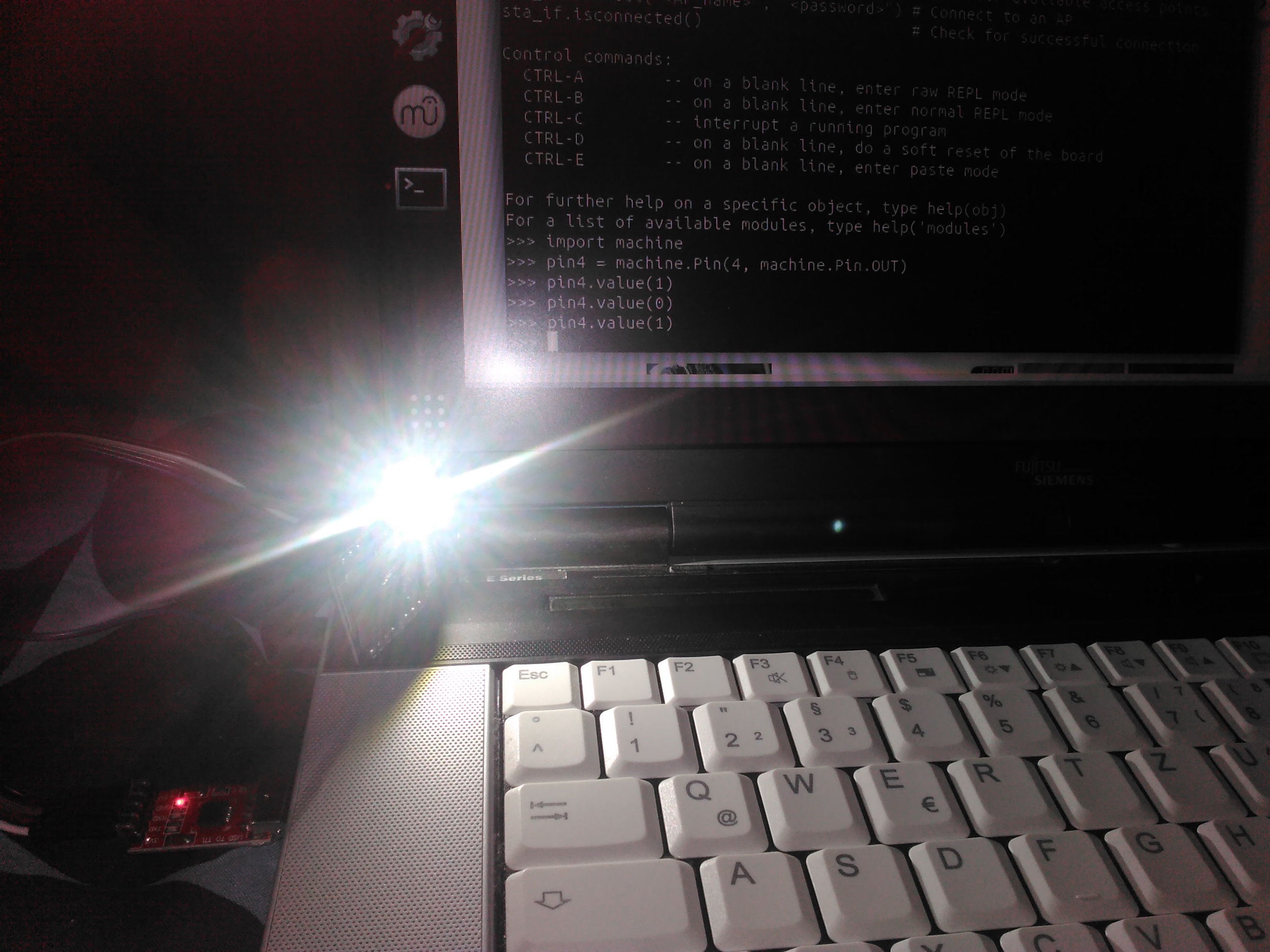
I started MicroPython pin toggling with GPIO4, which is connected to ESP32-CAM built-in flash lamp.
I was impressed by its brightness, it is so bright that you should not look into directly!
Image

User avatar
HermannSW
Posts: 97
Joined: Fri Oct 27, 2017 6:58 am
Location: Eberbach, Germany
Contact:

Re: ESP32-CAM ov2640 exposure control/FREX mode

Postby HermannSW » Mon Jun 24, 2019 10:07 am

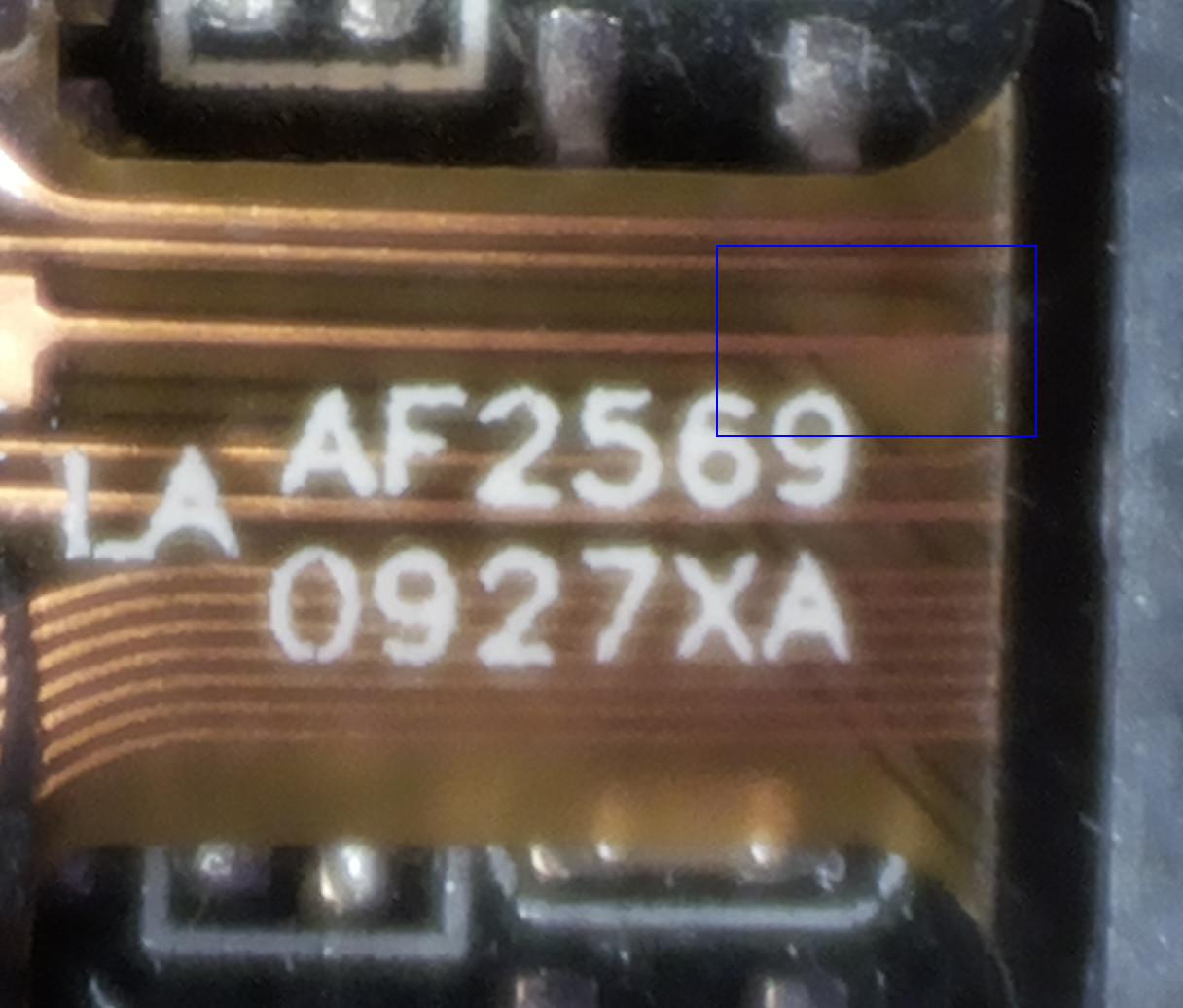
Hmmm, not sure whether it is possible to solder a thin cable to line on the flat ribbon cable.
At least there is an area with more space that 0.5mm spacing on the connector, and it is on the up side:
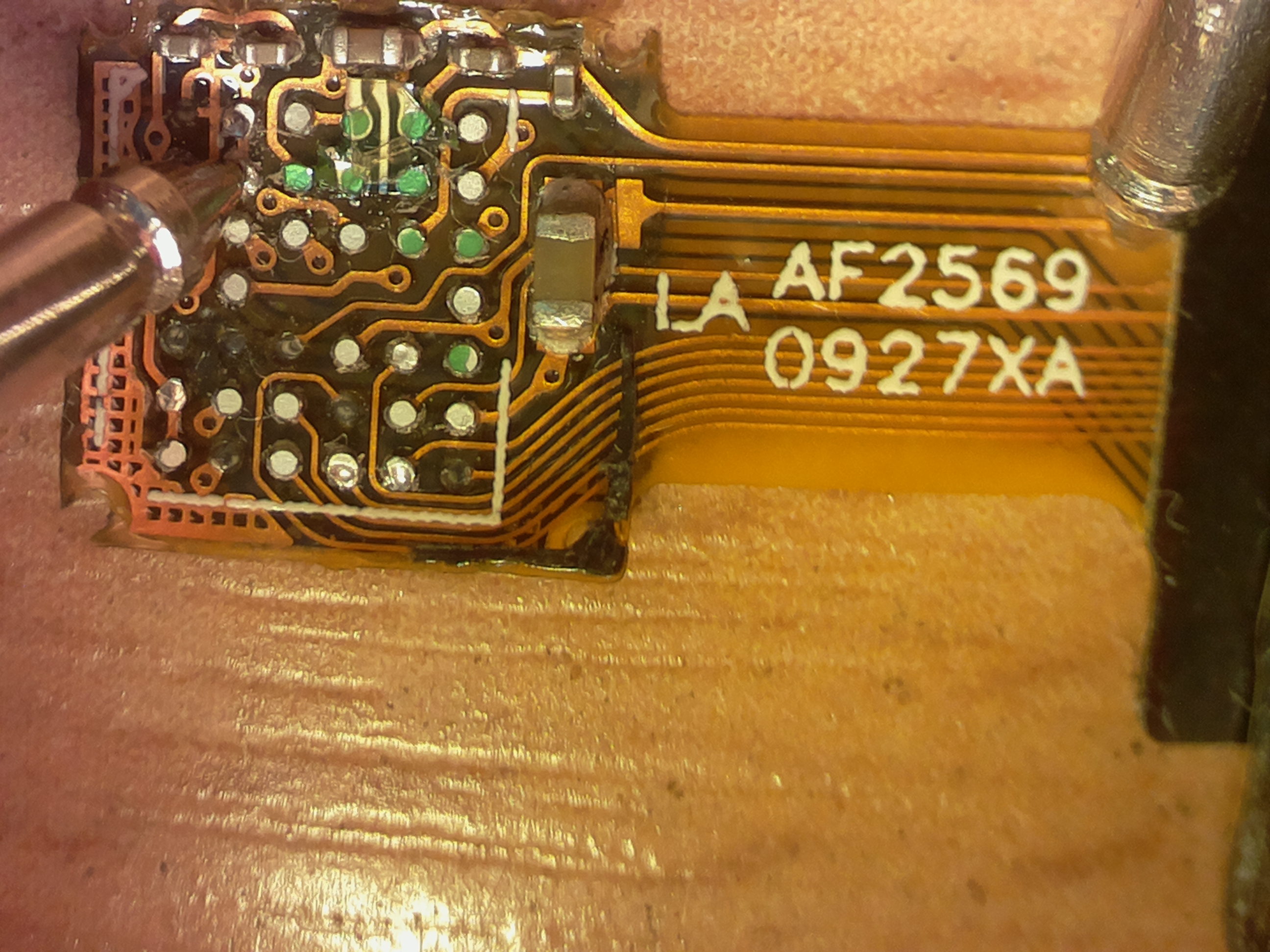
Image


Raspberry Pi microscope allows to get much more details (0.121µm/pixel resolution).
This is the line of interest at left border of blue rectangle above (right click to see full 8MP image):
https://www.raspberrypi.org/forums/view ... 0#p1409956
Image


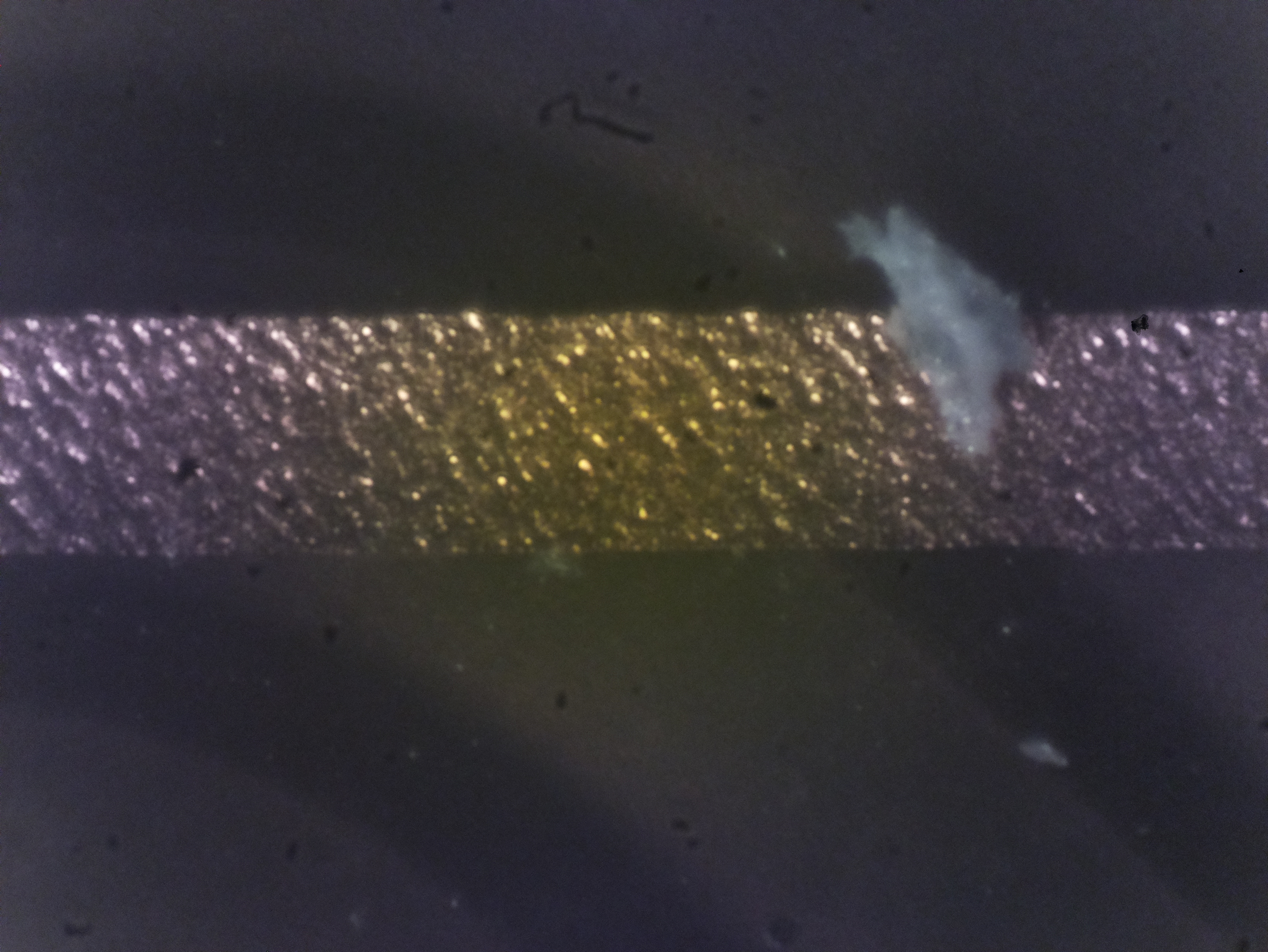
Cutting off plastic covering the line really allows ohmmeter probes to verify 0Ω between B2 and uncovered line!
Image


Cutting off a bit more plastic covering the line as preparation for soldering attempt. Now the uncovered area is so big that I was able to verify B2 contact with ohmmeter probes with just my eyes and no other help:
Image


Now the question is whether solder will connect to the uncovered line or not ...

User avatar
HermannSW
Posts: 97
Joined: Fri Oct 27, 2017 6:58 am
Location: Eberbach, Germany
Contact:

Re: ESP32-CAM ov2640 exposure control/FREX mode

Postby HermannSW » Mon Jun 24, 2019 11:26 pm

Trying to solder something to the uncovered wire was a flop.

I read that the size of soldering iron point should be not larger than the size of object to solder to. Despite that I only have 1mm Ø soldering iron and I am not good at soldering, I tried to solder cable to pin10 of flat ribbon connector on ESP32-CAM module. First I did test solder to one of the 24 pins of the spare connector I had. That worked surprisingly good. After many tries finally I was able to solder a cable to pin10. As stress relief I did put superglue on both sides of plastic around cable and glued that to ESP32-CAM board:
Image

First tests are good:
  • CameraWebServer.ino still works
  • no connection between pin10 and pin11/pin9
  • ohmmeter verified that cable end and sensor pin B2 are connected

ESP_Sprite
Posts: 9757
Joined: Thu Nov 26, 2015 4:08 am

Re: ESP32-CAM ov2640 exposure control/FREX mode

Postby ESP_Sprite » Tue Jun 25, 2019 2:23 am

I can't help you in your quest here, but I'd like it to be known that I highly enjoy reading about reading it here. Thanks for posting it in this much detail.

User avatar
HermannSW
Posts: 97
Joined: Fri Oct 27, 2017 6:58 am
Location: Eberbach, Germany
Contact:

Re: ESP32-CAM ov2640 exposure control/FREX mode

Postby HermannSW » Tue Jun 25, 2019 4:18 pm

Last night I did more experiments, and accidentally broke the soldered cable to pin10 connection.
It took some more tries to get the cable soldered to this tiny pin again.
Unfortunately that solding partly broke my ESP32-CAM board.
Flashing CameraWebServer.ino works fine, webserver boots up and serves the camera page.
Some communication with ov2640 still works, eg. the initial "is module there?" handshake.
But "Start Stream" does not work anymore :-(

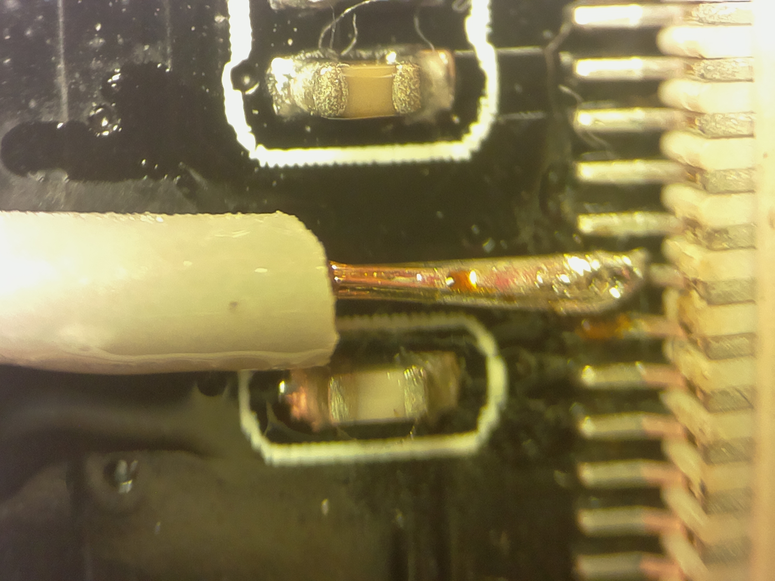
Despite having two ESP32-CAM modules only, and one not working with camera app anymore, I did risk my second module and did solder cable to connector pin10 today. Again with the help of Raspberry v1 camera HDMI monitor output as magnifying glass. I noticed problems to get solder onto a single wire, so I did cut off all but two wires from the cable today and did solder them. Then soldering cable to pin10 (after having fixated the cable end onto pin10 with my fingers lying on ESP32-CAM board (only 1cm(!) away from pin10 and the soldering iron) was just pressing down soldering iron, see solder melting and remove soldering iron. I never had soldered anything that quickly (I already said that I am not good at soldering), and the connection looks really good for me:
Image

Again I did use superglue for stress relief. Yesteday on the other module I did put a bit too much superglue onto the cable, and saw a flood of superglue moving all over the place and cover more than 10 pins. Today I used a very thin cable, dipped it into some supergle and then used the cable to fill the area between cable plastic and ESP32-CAM board. That way exactly the amount of superglue that was needed glued the cable to the board:
Image

As first test I connected ESP32-CAM module with USB2TTY adapter to laptop, opened the camera webpage and started streaming. Everything worked as it should!
Next I unplugged all cables and replaced the working ov2640 camera with the reduced connector from previous investigation. With ohmmeter probes I measured 0Ω between B2 and soldered cable end.

Next step:
Setup global external shutter environment, use ESP32-CAM instead of Raspberry v1 camera, connect some unused GPIO via soldered cable to FREX (B2) pin in ov2640 sensor, close moving box above the setup (to get it really dark), rise that pin to HIGH, then LOW (to trigger global reset frame capture) and use "shot" tool
https://github.com/Hermann-SW/Raspberry ... tools/shot
equivalent for taking a single flash.

I am pretty sure that when done correctly, although ov2640 sensor pins A2 and B2 are connected, a frame like this will be captured, perhaps with some lines at top of frame missing to show the 20000rpm rotating propeller (the propeller does 333 full rotations per second, and still gets captured as stand still) :
Image

Who is online

Users browsing this forum: Baidu [Spider] and 43 guests