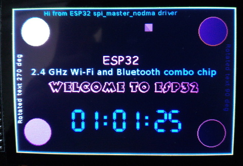
Non DMA version of the spi_master driver
Posted: Mon Mar 27, 2017 7:35 pm
Sometimes, using the spi driver not based on DMA transfer is more convenient.
I've created a new nonDMA spi_master driver (based on esp-idf spi_master) which is available on GitHub.
https://github.com/loboris/ESP32_SPI_MA ... MA_EXAMPLE
Main features
Example
To run the example, attach ILI9341 based display module to ESP32 at different spi clock speeds.
Default pins used are:
If you dont have the touch screen, comment #define USE_TOUCH in spi_master_demo.c
Using make menuconfig select tick rate 1000 ( → Component config → FreeRTOS → Tick rate (Hz) ) to get more accurate timings
This code tests accessing ILI9341 based display using spi_master_nodma driver and prints some timings.
I've created a new nonDMA spi_master driver (based on esp-idf spi_master) which is available on GitHub.
https://github.com/loboris/ESP32_SPI_MA ... MA_EXAMPLE
Main features
- Transfers data to SPI device in direct mode, not using DMA
- All configuration options (bus, device, transaction) are the same as in spi_master driver
- Transfers uses the semaphore (taken in select function & given in deselect function) to protect the transfer
- Number of the devices attached to the bus which uses hardware CS can be 3 (NO_CS)
- Additional devices which uses software CS can be attached to the bus, up to NO_DEV
- spi_bus_initialize & spi_bus_remove functions are removed, spi bus is initialized/removed in spi_bus_add_device/spi_bus_remove_device when needed
- spi_bus_add_device function has added parameter bus_config and automatically initializes spi bus device if not already initialized
- spi_bus_remove_device automatically removes spi bus device if no other devices are attached to it.
- Devices can have individual bus_configs, so different mosi, miso, sck pins can be configured for each device.
Reconfiguring the bus is done automaticaly in spi_device_select function - spi_device_select & spi_device_deselect functions handles devices configuration changes and software CS
- Some helper functions are added (get_speed, set_speed, ...)
- All structures are available in header file for easy creation of user low level spi functions. See tftfunc.c source for examples.
- Transimt and receive lenghts are limited only by available memory
- TRANSMIT 8-bit data to spi device from trans->tx_buffer or trans->tx_data (trans->lenght/8 bytes) and RECEIVE data to trans->rx_buffer or trans->rx_data (trans->rx_length/8 bytes)
- Lengths must be 8-bit multiples! (for now)
- If trans->rx_buffer is NULL or trans->rx_length is 0, only transmits data
- If trans->tx_buffer is NULL or trans->length is 0, only receives data
- If the device is in duplex mode (SPI_DEVICE_HALFDUPLEX flag not set), data are transmitted and received simultaneously.
- If the device is in half duplex mode (SPI_DEVICE_HALFDUPLEX flag is set), data are received after transmission
- address, command and dummy bits are transmitted before data phase if set in device's configuration and if trans->length and trans->rx_length are not both 0
- If configured, devices pre_cb callback is called before and post_cb after the transmission
- If device was not previously selected, it will be selected before transmission and deselected after transmission.
Example
To run the example, attach ILI9341 based display module to ESP32 at different spi clock speeds.
Default pins used are:
- mosi: 23
- miso: 19
- sck: 18
- CS: 5 (display CS)
- DC: 26 (display DC)
- TCS: 25 (touch screen CS)
If you dont have the touch screen, comment #define USE_TOUCH in spi_master_demo.c
Using make menuconfig select tick rate 1000 ( → Component config → FreeRTOS → Tick rate (Hz) ) to get more accurate timings
This code tests accessing ILI9341 based display using spi_master_nodma driver and prints some timings.
- Some fancy graphics is displayed on the ILI9341-based 320x240 LCD, lines, pixels and color bars.
- Sending individual pixels is more than 10 times faster with this driver than when using spi_master
- Reading the display content is demonstrated by comparing random sent and read color line.
- If Touch screen is available, reading the touch coordinates (non calibrated) is also demonstrated. Keep touching the display until the info is printed.
Code: Select all
===================================
spi_master_nodma demo, LoBo 03/2017
===================================

SPI: bus initialized
SPI: attached display device, speed=5000000
SPI: bus uses native pins: true
SPI: attached TS device, speed=2500000
SPI: display init...
OK
-------------
 Disp clock =  5.00 MHz ( 5.00)
      Lines =  1153  ms (240 lines of 320 pixels)
 Read check      OK, line 110
     Pixels =  2775  ms (320x240)
        Cls =   259  ms (320x240)
-------------
-------------
 Disp clock =  8.00 MHz ( 8.00)
      Lines =  1057  ms (240 lines of 320 pixels)
 Read check      OK, line 112
     Pixels =  1952  ms (320x240)
        Cls =   166  ms (320x240)
 Touched at (294,269) [row TS values]
-------------
-------------
 Disp clock = 16.00 MHz (16.00)
      Lines =   978  ms (240 lines of 320 pixels)
 Read check      OK, line 94
     Pixels =  1259  ms (320x240)
        Cls =    88  ms (320x240)
-------------
-------------
 Disp clock = 20.00 MHz (20.00)
      Lines =   962  ms (240 lines of 320 pixels)
 Read check      OK, line 190
     Pixels =  1118  ms (320x240)
        Cls =    73  ms (320x240)
 Touched at (1719,1710) [row TS values]
-------------
-------------
 Disp clock = 26.67 MHz (30.00)
      Lines =   946  ms (240 lines of 320 pixels)
 Read check      OK, line 151
     Pixels =   990  ms (320x240)
        Cls =    57  ms (320x240)
-------------
-------------
 Disp clock = 40.00 MHz (40.00)
      Lines =   930  ms (240 lines of 320 pixels)
 Read check      OK, line 25
     Pixels =   848  ms (320x240)
        Cls =    42  ms (320x240)
-------------
