I am referring to ESP32-S2 Saola-1 schematic:
https://docs.espressif.com/projects/esp ... -v1.2.html
My board isn't the latest so it has a single microUSB. The USB port section looks like this:
I see there are 4 resistors in the right side box. The two on top and bottom are connecting D- and D+ to CP2102, correct? If I remove them I can access the S2 USB-OTG via onboard microUSB connector because the middle two 0-ohm resistors connect the S2 USB OTG D- and D+ to the microUSB connector, also with 22pF caps (probably S2 USB OTG needs this value). Correct?
USB port section for ESP32-S2 saola dev board
-
ESP_Sprite
- Posts: 9770
- Joined: Thu Nov 26, 2015 4:08 am
Re: USB port section for ESP32-S2 saola dev board
Yes, but note the two middle resistors are marked NC and as such not placed. Best solution is to move the resistors from the outer to the inner positions.
Re: USB port section for ESP32-S2 saola dev board
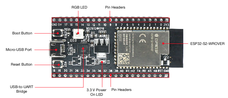
Thanks. I understand now. Here is a photo of my board on the official website:

It's hard to see the resistors. I have the resistors under a magnifier: The microUSB port is at the bottom of the image. I highlighted one resistor in blue and its new location in orange. So I need to move this resistor from blue to orange (also turn around), correct?

It's hard to see the resistors. I have the resistors under a magnifier: The microUSB port is at the bottom of the image. I highlighted one resistor in blue and its new location in orange. So I need to move this resistor from blue to orange (also turn around), correct?
Who is online
Users browsing this forum: No registered users and 78 guests
