Hi there board,
I'm designing a S3 SPI master board, that will feed some IT8951 with pixel data for some 9.7 epaper displays.
Schematics: https://github.com/martinberlin/H-cinre ... ematic.pdf
It has 2 USB-C's:
1 is for programming using USB - UART using CP2102
2 is for JTAG debugging
A good soul indicated me that CC* (Configuration mode) need 5.1K pull-down resistors.
My question is: Do also JTAG USB need this?
And also to enter USB debug mode does the board need to be in DFU Mode?
If that is a YES then I should add a second BOOT button since you need to press BOOT + RST in order to see the board being identified in the list usb.
Other than that if there is any interesting review here is how the PCB looks:
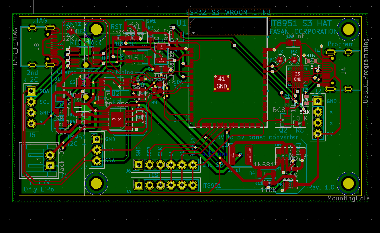
ESP32S3 PCB design with 2 USB-C
epdiy collaborator | http://fasani.de Fan of Espressif MCUs and electronic design
-
- Posts: 101
- Joined: Tue Mar 22, 2022 5:23 am
Re: ESP32S3 PCB design with 2 USB-C
Sorry, I do not have any experience of this design. If you get no fruitful response here, you can Post your design to https://www.pcbway.com/project/
PCB designers hang around there. Hopefully you'll get a proper direction.
Re: ESP32S3 PCB design with 2 USB-C
It's my understanding that you do need the CC pulldown's for the USB-JTAG connector as well, if you're using the USB connector as a possible power source (which your schematic indicates you are).
But I'm curious as to why you will be using 2 USB C connections for this. You _can_ use the USB-JTAG interface to do both programming and debug on the same interface, removing the need for the 2nd USB connector and the CP2102N IC.
Re: ESP32S3 PCB design with 2 USB-C
An extension of my previous answer -- USB C host ports will generally default to providing NO power. Adding pulldowns for CC1 and CC2 will indicate to the host what level of power should be provided. It won't matter if you're connecting to a Type A port (using Type-A to USB-C cable), since there's no upstream connections for CC1/CC2. But if you're going to connect to a USB C host port, those pins are needed to get power to your board.
https://community.silabs.com/s/article/ ... uage=en_US
Re: ESP32S3 PCB design with 2 USB-C
Awesome thanks for your reviews:
https://github.com/martinberlin/H-cinre ... ematic.pdf
- Added 5.1K pull-downs in CC USB-C pins to the schematic
- Added 10K pull-up to the INT interrupt pin of the DS3231, so actually ESP32 should wake up on the NIED_EDGE when the RTC connects the INT pin to GND
- Created new repository to add explanations and future code examples ( https://github.com/martinberlin/epaper-weather-station )
epdiy collaborator | http://fasani.de Fan of Espressif MCUs and electronic design
Re: ESP32S3 PCB design with 2 USB-C
hey fasani,
could you explain why you used a 5.1k pull down on the JtAG only on CC1 and left CC2 open?
And also the resistor at CC1 is not connected in delivery state.
Is the JTAG interface tested?
I would like to implement the same. The ESP32-S3 should also be supplied with power by the JTAG-USB (power and debug with 1 cable). So I thought I need both pull-downs at CC1 and CC2. Isn't that right?
EDIT: I found these clones on Aliexpress. Don't wonder about the link, this is the file server from vcc-gnd.com.
http://152.32.187.208:8080/yd-data/YD-ESP32-S3/
Pull-downs also for the JTAG. As you would expect if you want power supply
Official USB Type-C Cable and Connector Specification helped me to understand, page 247:
https://www.usb.org/document-library/us ... cification
Regards
Who is online
Users browsing this forum: Bing [Bot] and 104 guests