
I see this thread re tag-connect:
https://www.esp32.com/viewtopic.php?f=1 ... ect#p37922
- but can anyone share an exact and tested pinout / set-up for J-Link Segger / tag-connect (pref TC2030) / 2x5 pin?
My objective is development debug with the J-Link / 2x5 pin and production flash with the J-Link / tag-connect.
TIA, Alan
Exact Segger J-Link / jtag / tag-connect pinout?
-
AlanAmbrose
- Posts: 5
- Joined: Tue Mar 05, 2019 8:53 am
-
AlanAmbrose
- Posts: 5
- Joined: Tue Mar 05, 2019 8:53 am
Re: Exact Segger J-Link / jtag / tag-connect pinout?
Hmmm,
OK more info here:
https://docs.espressif.com/projects/esp ... ag-adapter
https://docs.espressif.com/projects/esp ... rover.html
- but this raises some more questions:
(1) The docs say:
"The JTAG port on the ESP32 is an industry-standard JTAG port which lacks (and does not need) the TRST pin."
"SRST can optionally be connected to the CH_PD of the ESP32, although for now, support in OpenOCD for that line is pretty minimal."
- but the WROVER JTAG shows:
ESP32 Pin JTAG Signal
CHIP_PU TRST_N
- suggesting that EN/CHIP_PU/TRST is actually used.
Question is - which is it?
(2) There's a 7x2 pinout show on the WROVER KIT schematic, but it shows two sets of jtag signals and some odd pull-up stuff for S_TDI whatever that is. So, e.g. there's MTDI, TDI and S_TDI on the jtag pinout. What gives? Which of these is actually used?
Alan
Re: Exact Segger J-Link / jtag / tag-connect pinout?
On the WROVER-KIT board, TRST (or SRST — it can be configured either way) is indeed brought out on a header next to ESP32's EN pin. However this is a provision for future SRST support, current version of OpenOCD for ESP32 does not utilize that.
Same goes for the S_TDI — this was initially added as a workaround for the conflict between GPIO12 strapping signal and a pull-up of the SD card; however nowadays OpenOCD can be configured to hold GPIO12 in the correct state when resetting the target.
Basically, you can use the remaining MTDI MTDO MTCK MTMS pins to connect your JTAG adapter. This is reflected in the photo on the following page, which shows which jumpers need to be installed to use JTAG:
https://docs.espressif.com/projects/esp ... up-options (this page is linked from https://docs.espressif.com/projects/esp ... rover.html).
I would suggest still breaking out EN, TX, RX, GPIO0 pins, in case you find that you need to use serial bootloader for some production step, such as burning Efuses or checking the UART output, should there be any issue.
-
AlanAmbrose
- Posts: 5
- Joined: Tue Mar 05, 2019 8:53 am
Re: Exact Segger J-Link / jtag / tag-connect pinout?
OK understand, and thanks for your detailed reply.
Alan
Alan
-
AlanAmbrose
- Posts: 5
- Joined: Tue Mar 05, 2019 8:53 am
Re: Exact Segger J-Link / jtag / tag-connect pinout?
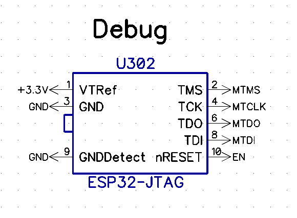
OK for anyone else looking at this, this is the pin out I used on a 5x2 connector.
Who is online
Users browsing this forum: No registered users and 62 guests